Inhibit PLC-5 RIO Rack Online?

kwsullivan

Member
Join Date
Oct 2012
Location
NY
Posts
4
My customer has a PLC-5/80 with 20+ RIO racks. They've asked me to remove one of the racks without shutting the system down. Can I set the respective rack inhibit bit online in Remote Run mode or do I have to set it offline and then download? Obviously, I'll remove or disable any respective block transfers first.


I'm told that its the last rack on the RIO link so I plan to just unplug the RIO LBT and leave the resistor connected. I haven't touched a PLC-5 in many years and I don't have any hardware to test this on.
 
PLC5 has no "declared" I/O, therefore no faults will be generated if any I/O hardware does not physically exist.

Any inputs from any disconnected "racks" will freeze at their last state. Tidy up if you feel the need.
 
My customer has a PLC-5/80 with 20+ RIO racks. They've asked me to remove one of the racks without shutting the system down. Can I set the respective rack inhibit bit online in Remote Run mode or do I have to set it offline and then download? Obviously, I'll remove or disable any respective block transfers first.


I'm told that its the last rack on the RIO link so I plan to just unplug the RIO LBT and leave the resistor connected. I haven't touched a PLC-5 in many years and I don't have any hardware to test this on.


as @kwsullivan mentioned, there is no 'inhibit'.


You are OK with removing the block transfers, making sure none of the IO is being used, turning the power off the rack, leaving the terminating resistor on the RIO connector, and unplugging that connector from the ASB.


I would also coil up the cable, tape it to the side of the cabinet, and put a BIG sign on it telling everyone that it will be removed as part of project # xxxxx (insert project number here) .. so that no one 'cleans it up' and shuts down the system.
 
RIO and DH+ are (were) one and the same, sharing the same hardware in terms of cable, connection plugs, transceivers, and terminating resistors, but the communications protocols were different. The only way to tell them apart was the colour coding of the cores on the blue cable.

I can't remember now but one of them went Blue-Shield-Clear, and the other went Clear-Shield-Blue. And if everyone stuck to that, all was well. But commissioning Joe knew that if a RIO or DH+ station wasn't communicating, you just swapped over the Blue and Clear insulated cores, the trick was to do that at the right end of the cable !! All of a sudden a DH+ network looks like RIO, and vice versa ! Of course, you have to remember that neither DH+ nor RIO could detect the colour of the cable insulation !!

Anyway, that's a digression from the thread. I just want to say that most people "daisy-chained" their RIO networks at the 3-pin plugs, putting both cables into the plug. Ever so slightly fugly IMHO.

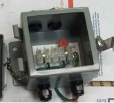
A "decent" RIO (or DH+) installation would have used "Station Connectors", which is a fancy name for a metal box with some connector blocks in. These allowed you to attach a single "drop-line" to your panel, much like the Controlnet "bus" system. Station Connectors could be used on RIO or DH+ interchangeably.

Most times the terminating resistor would be installed at the last station connector on the "bus", which although not technically correct, (because the T.R. was not at the end of the cable run to the device), was largely acceptable for the incredibly robust DH+/RIO technology !

It could be that the OP's RIO network used station connectors, and that removal of the cable would be a much easier job, rather than leaving it for a later project.

Having said that, it shouldn't be a hard job to trace the cable back and disconnect it at the previous "tap" onto the network, whether that was done by daisy-chaining, or by using Station Connectors. You just have to find out which panel (or Station Connector) the cable comes from, and disconnect accordingly, remembering to re-install the terminating resistor at the "end-of-line". Perhaps plan to do that on this project, and have no risk of someone just chopping the cable to remove the defunct panel ....

I once worked in a brewery that began to get RIO issues on on system, which came and went at seemingly regular times of the day, and they could not track down the cause. It turned out, and it was discovered during a site survey by RA, that a redundant panel in a remote location, had a "drop-line" going into it, which had been disconnected from the ASB, coiled up, and left in the bottom of the panel. The panel had been gutted, all the control gear, panel switches, HMI etc. had been removed. That process area was "washed-down" twice a day with high-pressure lances, leaving a nice puddle of water in the redundant panel, which the bare ends of the RIO cable enjoyed a twice-daily swim ....
 
A "decent" RIO (or DH+) installation would have used "Station Connectors", which is a fancy name for a metal box with some connector blocks in.
[/QUOTE

FYI, I believe the Station connectors had a capacitor in them also.

See PDF
 
A "decent" RIO (or DH+) installation would have used "Station Connectors", which is a fancy name for a metal box with some connector blocks in.
[/QUOTE

FYI, I believe the Station connectors had a capacitor in them also.

See PDF

The capacitor is between the shield termination and "frame ground", which makes it pretty "passive". It does not affect the signal wires in any way. It would be totally wrong to put any additional capacitance on the signal wires.

1770-SC.jpg
 
Interesting to note that the documentation for the 1770-SC says it is only used on DH or DH+ networks, and that is not the case.

As I said, DH+ and RIO are essentially the same network, so I see no reason why SC's cannot be used for RIO, in fact I have seen several installations where they were.

Also interesting is this from the documentation, which I cannot believe to be the case. How can a "junction" in the cable, that has no "device" connected to it, be considered a "node".

2021-01-17_074152.jpg
 
maybe they call it a node, implying logical, but the limitation addressed is actually physical i.e. electrical. Sort of like when laying out a system that can have a limited total cable length without an active repeater: connections count as an equivalent number of addition feet; or in fluid flow when chosing a pipe diameter capital cost vs. pump capital + operational cost, bends count as some equivalent number of feet of linear pipe.
 
maybe they call it a node, implying logical, but the limitation addressed is actually physical i.e. electrical. Sort of like when laying out a system that can have a limited total cable length without an active repeater: connections count as an equivalent number of addition feet; or in fluid flow when chosing a pipe diameter capital cost vs. pump capital + operational cost, bends count as some equivalent number of feet of linear pipe.

I could wire up a DH+ or RIO network with any number of junction boxes, spliced joints, station connectors, wire-nutted joints, even twisted wires, without the transceivers even noticing how many connections there are. So long as the total cable length is within the limits imposed it should be good to go, assuming the electrical connections are sound.

They specifically state "up to 64 nodes", implying that the DH+ modules of the RIO Scanners "see" those physical, electrical, connections as "nodes".

If they class an electrical connection as a "node", then you can only have 63 nodes on the network, because the 3 pin plug in the front of the scanner would count as a node, and we know that is not true.

Any electrical connections made do not eat into the allowed 64 addressable device nodes. If they did, how would you know what logical addresses the connections have "consumed" ?

If we are just joining cables together, then the cable itself could be considered to be an infinitely long chain of "nodes".
 
I may be jumping the gun , but better to raise a concern now.
even if you remove this rack from the program, the last state of the i/o is what is being read.
so the question is this,
1. is the remote rack that you want to remove configured to keep the outputs on when it is disconnected from the plc?
2. when you disconnect the rack, what will the plc program do in regards to the last i/o that was processed.

i will admit right now, that i am no expert and can be totally wrong in regards to my questions, as i said, better to ask questions now, rather than deal with somethings that goes sideways later.
james

What you say is quite true, any outputs that were written to a "1" in the output image table will remain there, waiting, lurking, for an unannounced connection of a new rack weeks, months, or years later.

Even if, and especially if, you have removed the code that drives those now defunct outputs, anything left ON is a potential time-bomb.

So, in days to come, you plan an extension to the system, and re-use those output addresses that were removed today, and decide to test the RIO comms before downloading the new program written specifically for those outputs, then those lurking "1"s will suddenly appear in the Output modules.

Safest to write all zeroes to the output data-tables after you have removed any code driving them. Think of it as potentially saving someone some harm, or a machine crash.

EDIT : and James, it has nothing to do with the module configurations, that comes into effect when the processor stops writing to the module, like when it goes into program mode or RIO comms gets broken. Output module data will be persistent in the processor data-tables regardless of module configuration (which incidentally was done in the RIO adapter, not in the output modules themselves).
 
Last edited:
....to follow on.

One thing I have to stress, because some people are not aware, is that ALL data-table memory is 100% retentive. It will survive power cycles, RUN/PROG mode changes, everything except a download, and it survives that also if you have "saved" the program with it's data.

"But my outputs go off if I re-start the program" I have heard said, but it is not because the data memory is non-retentive, it is because the processor does a "pre-scan" of the code, turning off all non-retentive outputs. This ensures that outputs will only be asserted by the "first-pass" of the code, making it safe.
 
I have seen some PLC-5 programs that will utilize the status of remote racks for control purposes. I would definitely search out the code for any such logic before proceeding. I specifically recall adding some logic like this to a system that I needed to halt due to a problem with a remote rack that was intermittent and would make faulty products if we let it run more than a few seconds without known good connection to one particular remote rack.
 
Thanks everyone. If the software prevents me from setting the inhibit bit online, it appears that the PLC shouldn't fault when I power the rack down. I have confirmed that none of the I/O points or status bits are used elsewhere in a way that would halt the system. I will reset all I/O bits once the associated logic is removed.
 
.... I will reset all I/O bits once the associated logic is removed.


After removing any code associated with the removed rack, you can easily use the File Fill (FLL) to clear all the output data in one hit.

The length will be 8 for each logical rack, and if your chassis is two, or four logical racks, 16 and 32 respectively. After letting the FLL(s) work, you can delete them.

You don't need to worry much about the Input data, that will assert itself if that rack is ever re-instated, although it's a moments work to duplicate the FLL, and address it to the Input Image table, just for completeness.
 

Similar Topics

Is there a way to change inhibit state of an IO card at the bit level? I know it can be done with modules via GSV/SSV But can it be done on...
Replies
8
Views
3,548
Question- Say I have 8 digital INPUTS to my PLC, any of which may be asserted HIGH for a few seconds, all these inputs "OR'd", currently, to...
Replies
16
Views
3,535
So everyone knows how to inhibit a module in studio or rs5000 I need to do the equivalent in tia portal 15. Need to run some test code but my...
Replies
4
Views
2,513
Good afternoon to all, I have a 1756-EN2TR PLC using studio 5000, along with a Kinetix 6500 (2094-EN02D-M01-S0) drive. This drive controls my...
Replies
8
Views
4,337
Is there a way to inhibit a module at the bit level? Instead of going into the properties and inhibiting the module it would be handy if you...
Replies
12
Views
12,968
Back
Top Bottom