A/B Analog Current Transmitter wiring dilemma

toddp65

Member
Join Date
Aug 2014
Location
Florence, Ky
Posts
282
Hello all,

I'm trying the wire up a Baumer Inductive Conductivity/Temp combination sensor to a 1769 combo analog in/out module.

The sensor is a new install; according the the manual print the transmitter uses the two 4 pin m13.
One side is for power and conductivity. Wiring as follows:

Brown: Supply+
White: Conductivity -
Blue: Supply -
Black: Conductivity +

the other connector (temp) is

White: Temp -
Black: Temp +

The other two wires on the cable/plug are for external input we're not using.


My connections on the analog card are V in + (1)
V in - (1)
I in + (1)


The way I have it currently wired I can monitor the input and it's fluctuating around -30,000. The sensor is already configured (the 4 and the 20) so by rights it should be reading 0 (the scaling is 0-32767 input min to max).

Thoughts on wiring this?
 
Looks like you will need to use 2) 4-20mA inputs. One for conductivity and the other for temp. The thing you need to find out is if the device supply’s the 4-20mA signal (Active) or if you need to supply the power from your panel (Passive). Once you know that we can help with the wiring.
 
Looks like you will need to use 2) 4-20mA inputs. One for conductivity and the other for temp. The thing you need to find out is if the device supply’s the 4-20mA signal (Active) or if you need to supply the power from your panel (Passive). Once you know that we can help with the wiring.
Thanks--yes, it has two separate cables. The conductivity side also provides the 24 vdc and it has cond + and - and uses all four wires.. The temp cable only uses two pins.I'm using inputs 1 and 3 on the card, they're already enable and configured on the module config.
 
Last edited:
Based on your data being negative, I suspect the polarity of the data wiring is backerdz.

We're still not clear on whether the signals are active or passive. Use a multimeter or loop calibrator to find out. With power applied to the device, test each pair with a meter (while unhooked from your PLC/panel wiring). If you get a mA reading with a multimeter or with a loop calibrator, then the device supplies the voltage for the signals. If you don't then you will need to apply 24vdc to the "+" wire, and you will get the mA data back on the "-" wire.

Note that some loop calibrators have a loop power mode. Don't use that mode at first, but if you get nothing, you can try loop power mode to prove that the signal works and that you need to wire it to a power supply (separately from the device power).
 
Last edited:
The black and white wires coming from transmitter conductivity side is reading 4 mA (that's what the display says it's transmitting as well, the line is empty) according to my analog meter. The temp is 5.6 (seems off).

So far it seems like a module wiring issue

when i swapped the wires, it went straight to -32767 and didn't move. In the other config it's -30,000 and fluctuating (still wrong)
 
Last edited:
Wiring as follows:

Brown: Supply+
White: Conductivity -
Blue: Supply -
Black: Conductivity +

the other connector (temp) is

White: Temp -
Black: Temp +


That certainly looks like a typical 4 wire transmitter, which wouldn't require a separate power supply for loop excitation. I suspect that the single power supply connection provides the loop excitation power for the temperature output as well as the conductivity output.

I'd need to know the exact part number and configuration of the IO module to specify the correct wiring, but if it's a 1769-IF4FXOF2F, then your output positive should probably connect to both the V in x+ and I in x+ terminals while the output negative would connect to the ANLG Com terminal.

that's the correct module number
 
I'll check the wiring; I know it's not like this but I've had it configured multiple ways.

Is it the diff or two wire current transmitter?
 
I would wire it up like they show the Differential Current Transmitter. Don't forget the jumpers they show in the diagram.
 
Yes..perhaps. But the scaling isn't true to the actual data. I've been trying to manipulate it to fit (ex: with 0-60 conductivity I've had to lower the max to bring my actual temp to what it is but when I go to what should be 0 it isn't accurate. Still playing with it. Odd thing is they value there whether the jumpers are installed or not.


Side note: I have these value ported over to the panelview plus--the tag is identical and it's worded the same way every other original numeric display is, yet I don't see it on my PVP after downloading it. Thoughts on this as well?
 
Last edited:
Figured out the PVP issue but the analog inputs are still incorrect. I have variables to work with but they're difficult to scale; the transmitter says it's sending out 4 mA but my engineering units coming in isn't the equivalent of 4 mA (3200) in my SCL block analog input (or in the controller tags tree ) it's like 3700.
 
Few more questions:

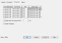
1. How do you have the Input set up? Raw/Proportional or Engineering Units? See the Attached snip.
2. Can you measure the actual current coming out of the instrument? It could be saying that it is sending 4mA but may be sending more due to calibration.
3. Any chance that you could be getting noise on the line? Do you have your shields grounded on one end only?

Analog Set up snip.png
 

Similar Topics

I am troubleshooting an actuator which is not responding to the plc code. The range in the channel of the Allen Bradley 1756-OF8 Analog card is...
Replies
1
Views
622
Hello My analog sensor outputs 4-20mA only. My analog PLC input sees 0-10V only. How can I make this work? I tested out a different sensor...
Replies
4
Views
1,783
Dear All, I want to use a 4-20mA output from Omron AO module, so I did the following configuration: PLC used CJ1M-CPU22, rack 00 CJ1W-AD041, rack...
Replies
13
Views
4,936
Hello guys, it's my first time getting my hands on a analog output: 0-10V; 0-20/4-20 mA and I lost my head a bit. I can read the 0-10Voltage range...
Replies
0
Views
1,942
Dear experts, i have a CT 600/5A and analog Amps meter 0-600A @2.5Class, 1)now i want to measure the same current to changing analog meter to...
Replies
1
Views
2,403
Back
Top Bottom