cdwilliams496
Member
All,
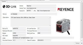
First all that for all help in trying to help me. I am currently testing different IO link devices with an AB Control Logix PLC. I am using a Logix 5585E processor, an 1732E-8IOLM12R AB IO Link Master and a Keyence LR-TB2000 distance laser on a test rack. I have attached (2) pictures of what I have so far.
I have configured the IO master correctly and I am seeing the feeback from the laser. Where I am getting lost is how the distance is coming back from the laser into the PLC. I can see values in IO_Link_ModuleI.Ch2Data[0]0 and IO_Link_ModuleI.Ch2Data[0]1 change as I move the laser from the target. But as I move, the value in Data[0]1 go from a positive to a negative number then back to positive. The number in Data[0]0 only increases as I move away from the target.
I was expecting the distance to just be in one register instead of across two registers. And why is one number increasing and decreasing.
What PLC command do I use to merge those two data registers together for an overall distance that I can use for calculations?
Again, thanks for all the help and suggestions.
Davis


