system diagram two tank system

david32

Member
Join Date
Nov 2003
Posts
3
I have a diagram that shows a 2 tank storage system. the pump is manually started by the operator. when the first tank is full, the circuit must be able to automatically fill the 2nd tank by opening a valve,which is actuated electrically. when the 2nd tank is full,the pump must automatically shut down and a "tank full" indicator will light.

any help would be appreciated to help me submit a report on this.

i.e: construction/operation of the plc`s and connections to the plc`s of the input devices such as flow sensors, proximity sensors and output devices Electrically operated flow control valves.

connect sensors

limitations and advantages of PLC`s compared to alternative control techniques.

flow chart of the system

ladder diagram of the system
 
Last edited:
...and don't forget the bill

I just received one invoice for one continuous oven, with burners, motors, belt speed variation and PID control.
I must choose the PLC, the HMI, and the SCADA and make the electrical panel. This also should communicate thru Internet.

Can you please do my work for me, for free?

DO YOUR HOMEWORK

There are many people here that will gladly help you if you have a real question. If I know this forum already, nobody will do the work for you.

João
 
David, write each of the five questions individually on the back of a twenty dollar bill (US Currency only - no Euros!) and send it to me by DHL courier. I will return my best effort at the answers by email within one week of receipt.

No cheating - only one question per twenty!
 
ok joao i understand.

i have been attempting this myself but i have only just begun learning plc`s and i would appreciate a bit feedback concerning my system.

i have tried to do the ladder diagram and this is what i have come up with:-


start stop full
---l l---l--l/l-----------l/l------(pump)
l
---l l---l
pump


pump? float sw1
---l l------l/l---------------(valve 1)open


float1 float2
---l l------l/l---------------(valve 2)open


float1 float2
---l l------l l---------------(full light)


-------------end--------------------------l


as i said any help on where i am going wrong would be appreciated


david
 
Looking good!


start stop Tank2
full
---[ ]-----|-[/]-----------[/]------(pump)
|
---[ ]-----|
pump

Tank 1
pump float sw1

---[ ]------[/]---------------(valve 1)open

Tank1 Tank2
pump float1 float sw2

---[ ]---[ ]------[/]---------------(valve 2)open


float1 float2
---[ ]------[ ]---------------(full light)


-------------end--------------------------


This might be a little better but your original code was pretty good. Just keep at it, you will get there! Write your own report!
 
Tom Jenkins said:
(US Currency only - no Euros!)

Tom

We still have the good ol' Pounds (£), we don't want that low value Euro monopoly money! (n)


Originally posted by David32
i have been attempting this myself but i have only just begun learning plc`s and i would appreciate a bit feedback concerning my system

David, that is exactly what we want to see here, you put some effort in, posted what you have so far and then the answers follow. If you want advice on your reports, do the same, post them here as an attachment and let people read it and give you feedback.

Good luck with your course,

Paul
 
Now that I've seen your work, David, the twenties are optional!

Seriously, you have a good start. This may differ slightly from the sequence you are being taught, but my typical stages in a project are:

1) I/O Point List - a list of every field device, it's signal level, and the I/O channel on the PLC to which it is wired

2) Loop description - a description of the major functions of hte system, any interlocks or limitations, any alarms, and any operator adjustable setpoints (used in lieu of flow chart for developin glogic - it is much easier to create and modify than a flow chart)

3) Electrical schematics

4) Program ladder logic

5) Flow chart (very often skipped - it is really only suited for documentation of logic for future trouble shooting)

P.S. Paul Lucas - the Euros are much prettier than our US money, but I have trouble buying a Coke with them at my local McDonalds! I can't say about the Brittish pound - my only experience was in Northern Ireland a few years ago, and all I saved for souveniers were some coins. My recollection, though, is that the queen looks better on the money than on the telly!
 
You did fine.

It's always the case that you have to "verbalize" the task.

Then what?

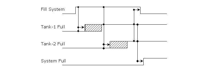
Try a timing diagram.

3fa6f5982c69cec3.gif


Create a timing diagram that shows the sequence of "causes & effects".
It doesn't have to be anything fancy... just reasonably accurate and complete at a conceptual level.

As time goes on, you will find more issues and concerns. Just slip them into the diagram as they should apply. You'll probably end up redrawing the diagram a few times as more of the issues become apparent.

If you run into a problem, refer back to your "timing blue-print".

As you look at the "timing blue-print" some questions become glaringly apparent...

What causes "Fill System"? Then what happens?

What causes "Tank-1 Full"? Then what happens?

What causes "Tank-2 Full"? Then what happens?

What causes "System Full"? Then what happens? (Go have a Beer!... I think)

It's just a way to organize your thoughts and perceptions. It helps - a lot!
 
thanx for the help everyone

thank you for your help on my problem everyone.

much appreciated

david
 
feedback

David
Try also to copy the actual status of the Pump and the two valves to the plc as a feedback for the safe operation of the system through feedback limit switches this is an important interlocks inyour system .
For example you can't oprate the pump tp fill tank while the valve is open.
Try It.
Bes luck :D
 

Similar Topics

the attached file is my system which is to be automated. the whole system is now manually run. could someone please tell me what plc i should use...
Replies
3
Views
1,991
Hello, I have no training in maintaining potable water systems, so forgive me if some of my terminology is far off the mark or if I'm focusing on...
Replies
0
Views
91
I have a redundant ControlLogix being set up. This program reads a value from a remote site which happens to be SLC PLC. Rockwell mentions SLC...
Replies
2
Views
94
Hi all, This is going to be a long post apologies. I'm also a complete beginner to the world of PLCs. I'm currently working on my first ever...
Replies
10
Views
445
Hello everyone, I'm working on a project that involves controlling an array of nozzles within a CNC environment, where the nozzles travel along a...
Replies
5
Views
176
Back
Top Bottom