Single phase motors

kalabdel

Member
Join Date
Feb 2015
Location
Ontario
Posts
1,108
Hello gentlemen,


A few questions regarding single phase motors:


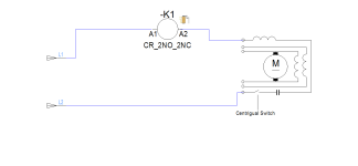
1- Would a relay wired as per attachment work? The idea (not new) is for the relay to energize for as long as the motor is stopped and the centrifugal switch is closed. I will solder a resistor across the capacitor to prevent the relay from shattering(also not new , seen it before with and without). I can get in the motor and wire the A2 of the relay coil directly to the other side of the switch but I would rather use the existing motor leads coming to the control panel.


2-What is a single phase instant reverse motor. Seen them, used them but haven't been able to get much information on how they're built nor can I get schematics for them.


3-Sigle phase dual speed motors: Similar question to the question above, how are they built and where can I get schematics for them.


Thanks
motor.png
 
2 - The single phase, instant reverse motor is basically like 2 permanent split capacitor motors in one. There are 2 windings and one run capacitor. Depending on which winding is connected directly, the other is fed through the capacitor, which gives the phase shift (2 phase motor, essentially). Since the windings are 90 degrees apart, the motor develops torque one way or the other, with the lead/lag of the current.

http://forums.mikeholt.com/attachment.php?attachmentid=6144&d=1324329677

This might be a better picture: http://tangerinepanic.com/wp-conten...ngle-phase-reversing-motor-wiring-diagram.jpg

I just realized that earlier one showed one on the windings beng reversed, which is not the way I am familiar with from Leeson: https://www.regalbeloit.com/Search?searchText=113642
 
What HP are you working with?
I think your drawing will produce a smoke show. Obviously may depend on the motor size but I highly doubt the relay coil will be able to handle the current from the start winding.


Instant reversing motors are designed to switch directions even if the motor is still freewheeling. On a standard single phase motor if the the motor has not coasted to a stop and the centrifugal switch is still open, starting the motor with the standard reverse connections will simply cause it to start the same way it was going as the start winding is out of the circuit.


Baldor has some information on their website...
https://www.baldor.com/brands/baldo.../ac-motors/farm-duty/instant-reversing-motors
 
What is the intended purpose of that relay in your diagram? Putting a simple relay in series with the motor start windings serves no purpose that I can see. What would happen is that (should it survive) it adds impedance to the circuit, effectively dropping the voltage seen by the motor, and motor torque drops by the square of the voltage drop. So it may cause your motor to stall.

Is this what you were maybe thinking? When you see what looks like a series relay in a single phase cap start motor, that is used IN LIEU OF the centrifugal switch. It’s called a “Potential Relay” and is specifically designed to energize at a specific voltage, coordinated to change state when the back EMF on the start winding hits a value that means the motor is at sufficient speed (80-90%) that the start winding is no longer needed, so the Potential Relay contact opens to isolate it. These are far far more expensive than a centrifugal switch but are used on motors, such as submersible pumps, where having to service a motor because a centrifugal switch went out would be prohibitively expensive.
 
Last edited:
Thanks everyone, that was very helpful. Anything on the dual speed single phase?


Instant reversing motors are designed to switch directions even if the motor is still freewheeling. On a standard single phase motor if the the motor has not coasted to a stop and the centrifugal switch is still open, starting the motor with the standard reverse connections will simply cause it to start the same way it was going as the start winding is out of the circuit.


Baldor has some information on their website...
https://www.baldor.com/brands/baldo.../ac-motors/farm-duty/instant-reversing-motors


Bingo, that's the reason for the relay.


1/2 of 3/4 HP. I've lifted this idea off a schematic twenty some odd years ago and haven't used it tow or three times back then and never since so I completely forget or rather was unsure. I found a schematic of a door opener and showing it's use as I described. Look for the relay marked "Motor Relay" and follow the wiring.


I even swiped a capacitor of an old door opener and will use that because it has the resistor soldered to it already. In my view it's a hoaky way of doing things and I would rather go with three phase or instant reverse motor but there's a long story behind it and this is the cheep way they want to go.


Thanks
 
What is the intended purpose of that relay in your diagram? Putting a simple relay in series with the motor start windings serves no purpose that I can see. What would happen is that (should it survive) it adds impedance to the circuit, effectively dropping the voltage seen by the motor, and motor torque drops by the square of the voltage drop. So it may cause your motor to stall.

Is this what you were maybe thinking? When you see what looks like a series relay in a single phase cap start motor, that is used IN LIEU OF the centrifugal switch. It’s called a “Potential Relay” and is specifically designed to energize at a specific voltage, coordinated to change state when the back EMF on the start winding hits a value that means the motor is at sufficient speed (80-90%) that the start winding is no longer needed, so the Potential Relay contact opens to isolate it. These are far far more expensive than a centrifugal switch but are used on motors, such as submersible pumps, where having to service a motor because a centrifugal switch went out would be prohibitively expensive.


Thanks jraef. What you wrote is very interesting and way beyond my knowledge. I will certainly read a bit more on the subject.


By the way I forgot to mention in my last post the relay type is HANDOUK GB-2C-A120T


Thanks a lot guys.


Kal
 
Yes, they are simple, single voltage motors. Being Permanent Split Capacitor designs, they do not need a start winding. They are essentially a 2 phase motor. This gives them a somewhat lower starting torque, but when sized properly, they last a good, long time, since there is no starting switch to wear out.
 
kalebdel, it doesn't seem like your pictures uploaded properly.
Now you have me curious how they are doing it in the door opener
 
Sorry that was the wrong link. I will try to upload the picture again.


That's not working, here's the correct link.
 
Last edited:

Similar Topics

What would happen if you ran a 60Hz Single Phase Motor on 50Hz supply?
Replies
6
Views
518
Hi PLCs.net! I'm working on a multi-motor system, most motors are single phase, driven by servo drives. I wanted to check what kind of motor...
Replies
11
Views
1,512
Any panel I've built with contactors and overloads has been 3 phase. I'm now quoting on one with some small single-phase loads. Definition of...
Replies
24
Views
5,585
Hello everyone, I ran into this 230 single phase two speed motor with two capacitors and a relay (see picture) and have a few questions: The...
Replies
4
Views
1,388
Good Morning , I should know this , but will a 3 Phase overload trip if a 3 Phase motor runs single phase for a long period of time ...
Replies
6
Views
2,171
Back
Top Bottom