Help with PID loop.

HoldenC

Member
Join Date
Sep 2012
Location
Cumberland, KY
Posts
219
I need a little help with a project I have been thinking about.

We have a belt line that is fed by a gravity door (pretty much a hydraulic gate in the ceiling). This gravity door gets plugged with material and the operator has to keep opening it up to 100% every few minutes to get it to start feeding again. I was wondering if it was possible to automate this process.

I was going to use the belt amps as a PV for this loop. The operators can adjust tonnage faster from the belt amps, rather than waiting for the material to hit the scales about 4 mins away.

Here is my problem. The gravity door is controlled by 2 PLC outputs. One is for closed, and one is for open. Im not sure how I could program a PID loop for this with 2 outputs.

I can upload a PDF of the logic if anyone needs it.
 
Can you describe the outputs better? What kind of outputs are they- analog or digital? What exactly are they controlling?
 
I am thinking that without position indication on the gate it will be very hard to use a PID.

This sounds like a similar control scheme to the digital control valves that I use in my business. There are 2 solenoids one for open and one for close. The flow rate from the flow meter is the PV for the system. The batch controller will manipulate the 2 solenoids to get the flow that is programmed into the system. The controller uses a "Tolerance Parameter" to determine if a flow adjustment is required. There is no valve position indication so the controller only knows the flow rate not the valve position.

Maybe you can do something similar. you may be able to use a PID instruction or you may be better to do it without it. Figure out what you want the SP to be and the Deadband you can deal with. If your PV is within Deadband then do nothing. If it is greater than Deadband then open the gate. Less than Deadband close the gate.

I think the major X-Factor in you being able to control the system will be how fast the gate moves. The faster it moves the harder it will be to keep the gate from oscillating open and closed. If you can make the gate move slowly it will make it easier to control. We install needle valves in our Digital Control Valves so that we can control how fast the valve moves when a solenoid is activated. Without them the valve will go full open to full closed so fast that the controller can't keep up.

Hope this helps.
 
PID is not what you are looking for in my opinion. You might want to try using a simple Limit instruction that reads the amp draw of the conveyor. If the amps drop, then cycle the door open and closed X number of times, then resume normal operation. Repeat as needed. Using a PID will be a lot more complicated, and just give you headaches you don't need.

Bubba.
 
There are PID controllers that do on/off (pulse) that change the on/off pulse width (or Mark/Space), however never seen one ready built in a PLC, you could use the Amps to control a pulse width modulator so for example if the amps increase, increase the length of the pulse for opening, if the amps fall reduce the pulse and if amps equal a pre set then turn off the pulse to hold the door in position (For 2 solenoids you would have to have an open/close pulses). Another solution is to use an inbuilt PID function, take the output value 0-100% and convert this to a pulse width modulation or on/off flip flops.
you would need a start value for example a set point i.e. if the amps when running normal say 6A then the set point would 6A, if the amps increase pulse on the open solenoid based on the difference above 6A, if it falls, below 6A then do the same for closed solenoid.
You would need to play with it to get the right settings and probably slug it a bit with timers but should be easy to do.
 
iirc I was looking at doing this as well, before other things had priority. I think I left off at using the polarity of the error signal from the PID as the enable to which solenoid (rung) gets enabled on the on off pulse output. Let me see if I can find where I left off with that....or maybe I *******ized the heating/cooling control theory with -100/100%...
 
Last edited:
Hello Holden,
please answer the following questions:
1. Does door have limit switches fully open and fully closed?
2. When operator press open/close button, does door go to end positions or door is moving only while the button is pressed?

PID is usually used with continuos variables, so it may be no optimal choise for this application, but it is still possible to use it. You can simulate and calculate % position of the door based on a measured time from fully open to fully closed position.
Parky explained already a lot, I'll just add my two cents.

There are PID implementations with discreete outputs. In fact, Siemens S7 300/400 has it in its standard library. Please have a look at FB42 step controller CONT_S. This type of PID is called three way step controller and it is made for motorised valve.

You need to determine the Setpoint for your PID control. PV is belt amps. You need to estimate (by repeated experiments) position of the door vs belt amps. PID outputs will open and close the gravity door. If door goes from fully open and fully closed positions then PID doesn't have sense. But if the position of door is possible to be "between open and closed", and pulse opening /closing a little bit is possible, then PID is possible.
 
Last edited:
I need a little help with a project I have been thinking about.

We have a belt line that is fed by a gravity door (pretty much a hydraulic gate in the ceiling). This gravity door gets plugged with material and the operator has to keep opening it up to 100% every few minutes to get it to start feeding again. I was wondering if it was possible to automate this process.

I was going to use the belt amps as a PV for this loop. The operators can adjust tonnage faster from the belt amps, rather than waiting for the material to hit the scales about 4 mins away.

Here is my problem. The gravity door is controlled by 2 PLC outputs. One is for closed, and one is for open. Im not sure how I could program a PID loop for this with 2 outputs.

I can upload a PDF of the logic if anyone needs it.

As has already been mentioned, there are methods available for using discrete output CV control with a PID controller.

That said, it appears to me that you will be applying a software patch to a hardware problem. To replicate what the operators are now doing manually, you won't even need a PID. You could do it within ladder logic.

I'd first look at correcting the problem with material flow through your gate. You might consider employing vibrators or air cannons to prevent blockage. Simply opening the gate in response to a plug may be an adequate response, but I am of the opinion that doing so introduces a transient process upset, at best. Wouldn't it be a better solution if you could find a way to alleviate the plugging, rather than reacting to it?
 
I need a little help with a project I have been thinking about.

We have a belt line that is fed by a gravity door (pretty much a hydraulic gate in the ceiling). This gravity door gets plugged with material and the operator has to keep opening it up to 100% every few minutes to get it to start feeding again. I was wondering if it was possible to automate this process.

I was going to use the belt amps as a PV for this loop. The operators can adjust tonnage faster from the belt amps, rather than waiting for the material to hit the scales about 4 mins away.

Here is my problem. The gravity door is controlled by 2 PLC outputs. One is for closed, and one is for open. Im not sure how I could program a PID loop for this with 2 outputs.

I can upload a PDF of the logic if anyone needs it.
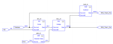
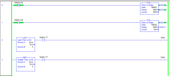
This is the framework of what I had completed. You can set the pulse width time and the error signal (SP-PV) modulates the timers for proportional control off Timer1.TT. It handles the core, but I still needed some ramp controls.

1.png 2.png
 
Sorry for the delay in replying, Ive been away for a couple days.

In response Pandiani's questions. Yes, the gate does have limit switches on both ends, and the unit only opens as long as you press the button.

In response to the comment by Bit_Bucket_07, i agree that this is a software patch for a hardware issue. I dont believe a vibrator would work in this process. The material actually stops above the gravity door.

An air cannon may be a good idea, but this project is just something im working on to make the operators job a little easier. I dont see anyone letting me spend any money for this.
 
This unit does have a posistion indication, however, Im still a little unsure how it works.

IM going over the logic, and looking at the RsView set up this morning.
 
Hello HoldenC,

Do you have a standard PID function block in the software library?
If you have a continuous PID, then, it is possible to make discrete two outputs (open/close) PID.

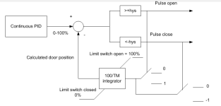
You can pretty accurately simulate door position in %. For example, measure how long door is going from fully close to full open and vice versa. You can use that time together with an integrator to simulate door position.
For example, if door needs 60 sec to go from 0 to 100%, then when operator press open butt, there will be 1.0 going into integrator with time constant 1.667 (60 sec x 1.667 = 100%). When operator release the push button, calculate position stays as is.
When operator press close button, then -1 goes to the integrator, and its output starts unwinding.

Therefore, in theory continuous PID can be used (control output 0 to 100%) , and then two compare blocks with some hysteresis . If PID's control output is for example 55% and door position (calculated) is 53% (hysteresis 2%), Open bit would be set until door position reaches 55% or controller output +hysteresis, and then open door output pulse would reset.

The same, when output from PID controller is bellow current calculated door position, closing pulse is generated until door position is within hysteresis of desired position (controller output).

Here is just a quick sketch how to convert continuous PID to PID with discrete outputs. Like I said earlier iput to the PID is control deviation that is formed like an error between setpoint and belt amps.
Setpoint you need to figure out or estimate.

PID-C_S.png
 
This is a 1 page of the PDF logic that seems to show what percentage the door is open.

I tried to upload the 8 pages that cover this gravity door, but it exceeds the upload size.

In RsView, there is a open and close button, and a display showing percent opened. I dont have access to the computer right now, but if I remember correctly, the open and close buttons add or subtract 2% from a tag known a "u37.position". The uploaded file shows this in logic, but im still not totally sure what is going on.

Ill have to check the RsLogix at that facility about the Standard PID and Continous PIDs. I dont have access where I am today..
Helo Holden,

unfortunately, I don't have any experience with Rslogix. I have only a limited experience with Siemens STEP7 programming software.
I hope you understand the general idea and I'm sure there are a lot of people here who would help when it comes to the actual software implementation.

Please have a look at the attached Siemens S7 discreete PID
 
Last edited:

Similar Topics

Hi all, I have a request from client as follows, There's one PID for Control valve which would be controlling on basis of temperature. One...
Replies
1
Views
1,513
Hi fellas, I have a Mitsubishi Q02 PLC and i need to setup a PID loop. I have downloaded the manual from mitsubishi and used there programming...
Replies
3
Views
2,575
Hi everyone...I just started a new job here in south boston va at Boehler-Uddeholm. After looking through some of there plc programs they seem to...
Replies
7
Views
2,656
Hi All, I am looking for some help, on writing a logic to control the Power output from a VFD using PID... I will appreciate your help...
Replies
3
Views
2,598
Can anybody tell me what exactly what pid stands for and what each letter does for the process.
Replies
8
Views
3,942
Back
Top Bottom