

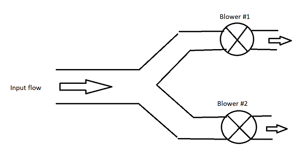
I have the control system that should control two blowers by one common input flow set point. I painted the simple picture, see the attachment.
What is the best practice for such a control loop? Is it one PID? Is it two separate PIDs that have the same SP? Maybe have I do one main PID that controls two cascaded PIDs? Or something else?
Could anyone let me links, references, articles, etc. that could clarify how to design such control systems?

