You are using an out of date browser. It may not display this or other websites correctly.
You should upgrade or use an alternative browser.
You should upgrade or use an alternative browser.
Toshiba EX100 Programming Access Help
- Thread starter daleroe
- Start date
Byron
Lifetime Supporting Member
From BnB's page: (PASSIVE versus ACTIVE) ???
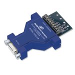
RS-232/422/485 CURRENT LOOP CONVERTERS
High speed optical isolators couple and isolate transmit and receive data. All B&B current loop converters have a transmit (T+ and T-) and a receive (R+ and R-) loop. Each loop may be operated as an active or passive loop. When the converter needs to provide the loop current, a 12 VDC power supply is required for the current loop side. Maximum baud rate recommended for current loop converters is 19.2 kbps.
All RS-232/422/485 current loop converter models are optically isolated
Designed for 20 mA Digital Current Loop. Inquire about other values
Maximum baud rate: 19.2 kbps
Models 232CL4R is a port powered RS-232 to current loop converter. No external power required for passive loop installations. A power supply is required to generate an active loop.
Model 232PCLR is an RS-232 to current loop converter that requires a power supply for the RS-232 side of the converter.
http://www.bb-elec.com/Products/Serial-Connectivity/Serial-Converters/Current-Loop-Converters.aspx
Model 232CLDR is a DIN Rail mountable, wide temp version for industrial applications.
These units are DIGITAL Current Loop, NOT for ANALOG Current Loop (0 to 20mA or 4-20mA)
Byron
Lifetime Supporting Member
Byron
Lifetime Supporting Member
<BTW> I found the FUJITSU cable ends on some old IDEC equipment I had for the old FA1J and FA2J PLC's...
Byron
Lifetime Supporting Member
@Byron,
Click on the below link to see Daleroe's collection of info.
http://gtprototype.com/plc/toshiba_ex100/
Click on the below link to see Daleroe's collection of info.
http://gtprototype.com/plc/toshiba_ex100/
Byron
Lifetime Supporting Member
Thanks! Yes I did download it all a couple nights ago. What I missed about the whole thing is the difference between a Control Loop versus just RS-422/485... I didn't notice the difference between the "Program Port" and the "Computer Link" terminal strip.
I am hoping the BnB 232CL9R will do the trick for the "Program Port". I have another rack coming in about a week and a half or so, from eBay, and it has the enhanced CPU.
I am hoping the BnB 232CL9R will do the trick for the "Program Port". I have another rack coming in about a week and a half or so, from eBay, and it has the enhanced CPU.
Last edited:
Byron
Lifetime Supporting Member
Current loop converter update
The BnB Current Loop Converter is on it's way.
BnB sent this update: (I enjoy history and especially history about industrial automation... thought I'd share this)
Our model 232CL9R can be configured to be an Active Current loop , or
a passive Current loop.
An internal resistor network is used to create a 20mA source if needed.
Below is a link to our Current loop Application note.
http://www.bb-elec.com/Learning-Cen...rrent-Loop/Current-Loop-Application-Note.aspx
CURRENT LOOP APPLICATION NOTE
The purpose of this current loop application note is to introduce the reader to the physical aspects of 20 mA current loop communications.
Until the early 1960's, military teleprinters used 60 ma current loops to communicate over long distances. In 1962, the Model 33 teletype was introduced and 20 mA current loop interfaces became widely used. Throughout the 60's, 70's, and early 80's, 20 mA current loop interfaces were applied in many types of equipment. Current loop interfaces became popular at this time because they offered the most cost effective approach to long distance, noise immune data transmission. The 20 mA current loop is suitable for distances to 2000 feet at data rates up to 19.2k baud with careful attention to interface design. It can be used at longer distances when data rates are as low as 300 baud.
When the EIA 422 Standard (December 1978) and the EIA 485 Standard (April 1983) brought forth the application of balanced differential digital data transmission, the popularity of 20 mA current loop rapidly diminished.
Download it below.
http://www.bb-elec.com/Learning-Cen...op/Current-Loop-Application-Note/curentlp.pdf
Last edited:
Byron
Lifetime Supporting Member
Question: How did you add module...
How did you add the module in without accessing hardware configuration in the software, or does the Toshiba PU11A automatically add modules in with a power cycle? Just curious.
Hello,
I am working on a Toshiba EX100 that I need to extract the ladder logic. I'm at the end of my rope. Any help is greatly appreciated. Thank you in advance.
Sincerely
Dale
Here are the details:
I'll be as detailed as I can and list part numbers for anyone else who finds themselves in my shoes.
The CPU is a PU11A (EX10-MPU11A).
I am unable to locate a programmer. I have searched for the following:
GP110 (EX25UGP-110)
GP110AP1 (EX25UG-110-AP1)
HP100 (EX25UHP-100)
MP100 (EX25UMP-100)
I have also tried unsuccessfully to locate a current loop converter (EX25GP232A-TIC2) or a schematic to build one.
Since the PU11A doesn't have the computer link RS-485 built in, I added a CL11 (EX10-MCL11) computer link module in the rack in hopes to access the ladder logic via the RS-485 on it.
I have a WIN98 laptop with a serial port (RS-232). I have an Advantech ADAM-4520 isolated RS-232 to RS-422/485 converter.
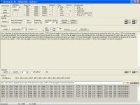
I powered the converter with 24vdc from the PS51 (EX10-MPS51) power supply module. I have tried every configuration imaginable to interface with the EX100 and have been unsuccessful using EXPDD250-V3. I also tried the QBasic Computer Link Test 0 listed in the appendix of the Computer Link-Function EX100 Users Manual to no avail.
How did you add the module in without accessing hardware configuration in the software, or does the Toshiba PU11A automatically add modules in with a power cycle? Just curious.
Last edited:
Byron
Lifetime Supporting Member
Using the BnB 232CL9R to replace Toshiba EX25GP232A-TIC2
Greetings Guys,
I uploaded a 3 page PDF with diagrams and questions for BnB... I'm still waiting on a reply. My EX100 PLC test rack is coming tomorrow but my EX25GP232A-TIC2 cable won't be here till the following week (hopefully), it is coming from Britain.
So in the mean time I am trying to see how I can make this BnB converter module work. I am open for ideas.
I went onsite and still got the same error messages of no communication. I used a 9 pin serial tester to watch the lights. Nothing comes back from the PLC as far as I can tell. My laptop is polling the PLC... no reply.
I could be wrong here but I believe you need to connect the A2B2 +5 from the PLC to the +12VDC connection of the converter to establish the complete current path. Whether or not the +5 is enough is just a guess, I don't know the voltage requirements of the chip inside the converter. Again, all this is guessing, I know the wiring on the DIY device works. My best advice would be to build the DIY device.
Edit:
Is there any way to positively identify the chip used in the BnB converter? With that info, maybe we can determine exactly what is needed to make the converter work.
Edit:
Is there any way to positively identify the chip used in the BnB converter? With that info, maybe we can determine exactly what is needed to make the converter work.
Last edited:
Byron
Lifetime Supporting Member
I could be wrong here but I believe you need to connect the A2B2 +5 from the PLC to the +12VDC connection of the converter to establish the complete current path. Whether or not the +5 is enough is just a guess, I don't know the voltage requirements of the chip inside the converter. Again, all this is guessing, I know the wiring on the DIY device works. My best advice would be to build the DIY device.
Edit:
Is there any way to positively identify the chip used in the BnB converter? With that info, maybe we can determine exactly what is needed to make the converter work.
**********thank you for the ideas***********
here is some transcript from my tech support from BnB:
******************************************
[22 Jun 2015 10:28:12]
To: Byron Sanders
The 232CL9R can be port powered, or externally powered.
If an LED tester is put in line on the RS-232 side, then the converter will require external power , ( +12V , GND )
I do not fully understand what is being shown on page 3 of the pdf.
If page 1 of the pdf is showing the connection of the PLC to our 232CL9R, The illustration on page 1 indicates that the PLC connection is ACTIVE.
*********my response a few minutes ago follows**********
Okay... so by using the RS232 TESTER, I have inadvertently isolated the power? A Toshiba EX100 rack from eBay is arriving today. I will try it without the tester in line.
Page 3 is a diagram for a DIY (Do It Yourself) converter that someone put together on PLCTALK.NET PLC FORUM that works. I put the diagram on page 3 of the PDF in hopes someone there at BnB Electronics might understand it enough to compare to what I am trying to do with the 232CL9R converter. I received a comment late yesterday on the forum. Here is my question and then the comment to my question:
********BYRON********
Using the BnB 232CL9R to replace Toshiba EX25GP232A-TIC2
Greetings Guys,
I uploaded a 3 page PDF with diagrams and questions for BnB... I'm still waiting on a reply. My EX100 PLC test rack is coming tomorrow but my EX25GP232A-TIC2 cable won't be here till the following week (hopefully), it is coming from Britain.
So in the mean time I am trying to see how I can make this BnB converter module work. I am open for ideas.
I went onsite and still got the same error messages of no communication. I used a 9 pin serial tester to watch the lights. Nothing comes back from the PLC as far as I can tell. My laptop is polling the PLC... no reply.
*****COMMENT*****
I could be wrong here but I believe you need to connect the A2B2 +5 from the PLC to the +12VDC connection of the converter to establish the complete current path. Whether or not the +5 is enough is just a guess, I don't know the voltage requirements of the chip inside the converter. Again, all this is guessing, I know the wiring on the DIY device works. My best advice would be to build the DIY device.
Edit:
Is there any way to positively identify the chip used in the BnB converter? With that info, maybe we can determine exactly what is needed to make the converter work.
*****END COMMENT*****
Here is a link to the page: http://www.plctalk.net/qanda/showthread.php?p=646984#post646984
Byron
Lifetime Supporting Member
jrwb4gbm: Thanks for the ideas. I am hoping to make the 232CL9R converter work so as to not have to build the converter ... in other words IF there is an off the shelf solution I want to share it with the world! Some day there will be NO MORE of these EX100 PU11A CPU's in the field, but until they are all replaced SOME OF US have to be able to provide support. Some clients don't want to change. I still support Westinghouse, Siemens S5, GE Series One, T1505, etc... Some client's cannot afford the down time right now either.
EDIT: you said... "My best advice would be to build the DIY device."
I want to do that as well for the experience.
EDIT: you said... "My best advice would be to build the DIY device."
I want to do that as well for the experience.
Last edited:
Byron
Lifetime Supporting Member
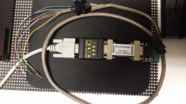
I'd love to see a picture of the unit that Daleroe built. A picture is worth a thousand words, as they say...
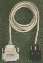
Here is a picture of the unit coming from England off of eBay:
(obviously there is NO EXTERNAL POWER SUPPLY on this unit. Which makes me believe the PLC PORT IS ACTIVE by means of the +5volt terminals but I don't know WHERE to place the +5, and I don't want to fry the system with 12 volt!) ( I figure there must be a way to look at the DIY diagram, the 232CL9R diagram and make an informed decision)

Last edited:
Byron
Lifetime Supporting Member
BnB_232CL9R_to_EX100_PU11A_ATTEMPT.png
Attached is my diagram from the PDF I uploaded: my FIRST ATTEMPT...
My nagging question, where to put the +5vdc ??? Or if 12 vdc is used, where? How do I keep from frying the PLC?
(If I want to put the 232 tester in series to see what is going on, how do I power it?
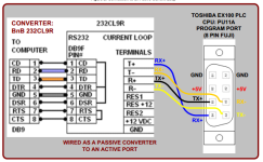
Attached is my diagram from the PDF I uploaded: my FIRST ATTEMPT...
My nagging question, where to put the +5vdc ??? Or if 12 vdc is used, where? How do I keep from frying the PLC?
(If I want to put the 232 tester in series to see what is going on, how do I power it?

Last edited:
Similar Topics
Hi
I'm having a bit of trouble finding a programmming cable for a toshiba EX100. None left with toshiba according to our suppliers.
Can anyone...
- Replies
- 7
- Views
- 9,041
We are using Toshiba ex100 plc. Please kindly suggest how to connect to the plc programming port via EXPDD250 software (version 3). I know that i...
- Replies
- 7
- Views
- 13,217
Another software thread!
We have a Toshiba EX100 that's just been working away quietly in a panel for 20 years, never causing a problem to...
- Replies
- 1
- Views
- 1,198
Hi, does anybody know if a HMI can be used with an old Toshiba EX100 PLC and if so which one? I cannot find any driver in the E-Designer software...
- Replies
- 4
- Views
- 1,661
We have a few machines here that have Toshiba EX100 PLCs in them. I found a programming cable with hardware dongle on Ebay. I am getting a no...
- Replies
- 13
- Views
- 5,253


