SLC 500 Pressure test

chopperprop

Member
Join Date
Nov 2015
Location
Missouri
Posts
22
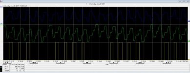
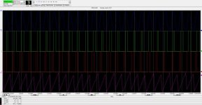
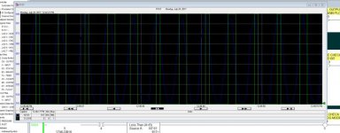
I am having trouble capturing data from an encoder when comparing it to an analog signal from a pressure sensor. The Pressure wave in the trend is consistent for every stroke of the machine as I am measuring a rise and fall of pressure with a pressure transducer 4-20 ma signal input to a analog input card being processed by a 1747-L551 processor. I am using a 960 gray code encoder being changed in the ladder logic to a decimal conversion and opening a window to look at the pressure when the machine is in a certain position. The problem is that the output bit for the window is not consistent with every stroke of the machine. When the pressure wave is at its peak position i need to capture the reading,and when comparing the pressure to the output bit and the overall rise and fall of the encoder signal the window shows up at different times.
Encoder, Pressure sensor are on the same rack as the processor.
Thanks in advance for any help on this.
 
so what is the exact problem the encoder is inconsistent with machine stroke or not matching up with pressure.

for encoder being inconsistent I would check the module update rate that it is wired to versus the rate of my incoming pulses if your module is not fast enough you will miss pulses hence get sporadic readings.

For pressure not lining up with encoder again depending on speed of machine the response time of your transducer may be to slow, this would most likely soft as a constant offset
 
you have left off the most important details.

1. what is making the stroke ? air cylinder, hydraulic cylinder, punchpress?

2. what are you pushing against?

3. what is the support of the backstop made of and how thick is it?

4. does any of your system flex?

I would not start to answer your question until I know these answers.
been bitten too many times without these answers.

james
 
Pressure Vs Time

you have left off the most important details.

1. what is making the stroke ? air cylinder, hydraulic cylinder, punchpress?

2. what are you pushing against?

3. what is the support of the backstop made of and how thick is it?

4. does any of your system flex?

I would not start to answer your question until I know these answers.
been bitten too many times without these answers.

james

Ok This is a 2 spindle machine the bottom spindle moves up into a seal that is cone shaped with a hole through the center the spindle has 4 slots at the tip and I am pushing air pressure through the slots at about 60 PSI from a regulator using a 1/4 inch tubing that is Teed at just before the bottom of the spindle and hooked to a 4-20 ma pressure transducer- sending a signal to my PLC SLC 505 L551 - I have an encoder on the shaft counting 1-1024for my position of the spindle so at approx. 113-338 for slow speed and 300-500 for fast speed approx. 160 PPM - during the open window I measure the pressure read out. I found that I had to have both JOG and RUN Fast speed windows to make it work. For the most part it works but I need 100 percent accuracy.
Is there a better way with what I have?
Also sorry I am slow at responding. I could give and excuse but that would not help.
Thanks
 
ok.

this is a 2 spindle machine, therefore 2 machines.
I am assuming each has the system you described, correct me if I am wrong.

anyhow,
you have 2 different spindles, seals, operating mechanisms, valves, and so on.
as far as I know, the two systems will never measure the same, you can get close.

why.
none of the components of the 2 spindle systems are identical ! End of discussion and you will never win that argument. there are differences in the spindles, bearings, bearing grease, sticktion (friction) of each mechanism, the seals are different. even though you say they are the same part number, no two parts are identical, we are talking +/- 0.0005"

you also have machine differences, the 2 are not assembled identically.
they move as they operate and eventually slip.

what you can do is this.
take a station, take it apart, clean the unit, I mean spotless. use indicator gauges to confirm the alignment. tighten down the system and dry run it.
then check the system again. then run some parts and recheck the system. if nothing moved, drill holes in the unit and put in dowell pins or spring pins (not as accurate and can still move).
repeat for the other unit.

then take each piece of tubing and coupling and make them the same length, if one has to have 3ft of tubing coiled up, so be it.

calibrate each regulator (assuming proportional valve) using a multimeter with an fet input. I use fluke 87 and the same power device. make the output the same.
calibrate the inputs using a simulator if possible. each input will be calibrated the same, but the input data may vary.

you will then have to measure the force and distance accurately for each system. this will take 100 tests or more to see what offset you will need to put into the program. then adjust your pressure and rerun the tests over for each machine.

long winded post and time consuming, but this is as accurate as you will get.

My background - 11 years working for an oem building automotive test equipment as the electrical engineer, designer, and programmer.

regards,
james
 
Last edited:
Everyone,

I do apologize, my last post was a bit harsh and could have been written in a more graceful manner. I have never been one to beat around the bush and it comes out wrong, in speech and in writing. again, I do apologize.

james
 
No worries- I should have been clearer on the application I have put together a series of 5 short videos of what I am measuring and when with the PLC logic.
I am only using the bottom station to measure pressure at a time interval specified by the encoder attached to the bottom shaft the gearbox that is driving the lower station or spindle.

https://youtu.be/lGwp71Rsn1o

https://youtu.be/Q2Qj4lxxKPw

https://youtu.be/dAdplsOdlBA

https://youtu.be/PYYSx99yw2I

https://youtu.be/fyRQaoh30MM

I changed the graph colors to make it easier to read.

https://youtu.be/cER96UcZQGw

https://youtu.be/So6EQpi3x5o
 
Last edited:

Similar Topics

I have a program that I've used 100 times. SQO settings: File N7:0, Mask 0FFFFh, Dest B3:1, Control R6:0, Length 8, Pos 2. Length & Position...
Replies
48
Views
925
Everyone, i am in the process of purchasing the Slc 500 version of software to support what we have and i have a question. Several of our...
Replies
9
Views
737
In a slc 500 plc I am trying to move data with out using a lot of moves. I want to move data from n7:1 to n7:2 and data that was in n7:2 to n7:3...
Replies
16
Views
1,340
Customer has a circa 2004 SLC-500 PLC. Fieldbus is a 1747-SDN DeviceNet scanner. Customer has SLC-500 file (.rss) with no comments. Has no *.dnt...
Replies
7
Views
543
After I tried wiring, I used computer program communication to read the PLC N value, but received a NAK signal. And the DL3500 CHA light keeps...
Replies
0
Views
416
Back
Top Bottom