Cj1m As Master, Cpm1a As Slave, How To Com?

neorder

Member
Join Date
Aug 2004
Posts
5
hi, i'm new to PLC and just found this website today, i'm so excited to see this website :oops: okay, i'm studying degree in real estate, but my company is doing a lot BAS system, we use most DDCs not PLCs, eventually no one in our company knows PLCs.

recently our company got a new project, and it was handled to me, the customer insist to use PLCs, so we approched local Omron vender, they recommanded us to use a CJ1M PLC as a master, 10 CPM1A PLCs as slaves, all together there are 11 PLCs in this project.

i think the slave PLCs are easy to program, mostly we do monitoring only, here comes the problems,

the CJ1M will be the master PLC, it has 2 additional modules each has a 422 and 232 port, they will be linked to 4 network, each network will have 2,3 CPM1A PLC. so do i still use CX programmer to program CJ1M? how do i set it up as the master collecting information and transfer to a NS 12" PT?

i think PLC ladder program is harder than DDC's FBD program we are using, but it's quite interesting and challeging. :rolleyes:

hope i can get a more clear image about this project asap.

thanks,
 
neorder,

Yes, according to the Omron manual, you use the 'CX Programmer version 3.0 or later' software "which supports the entire Omron PLC product line".

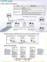
The CJ1M Master CPU module is automatically the Master PLC and it can access data from 9 nodes on the Serial PLC Link. Ther are two methods of setting it up, the "ALL Node Link Method", or the "Master Link Method". I think that if you wnt to use a 12" NT/NS series operator terminal, you need to use the Master Link connection method. The terminal becomes one of the slave nodes, and can echange data with the Master CJ1M only. The CJ1M Master automatically receives data from up to 9 nodes or slave PLC's. It can send only 10 words of data to each of the other 9 nodes.
 
thanks lancie

i've a few more questions regarding these two PLC.

1. the CPM1A does have a 24VDC/.2A output voltage, when i want to use CDT which means the output are transistor output(it consume 0.9A per output), do i need to connect extenal DC supply?

and when i use relay output(10mA each output), i don't need to connect extenal 24VDC power, am i right? one of my collegue insist to use a extenal 24VDC supply, will it overload the circuit?

2. you are saying the CJ1M can only connect to 9 notes? but i've more than 9.i've 8X10CDR, 1x20CDR, 1X30CDR plus the PT, all together is 11nodes.

we actually have 2 additional modules in CJ1M called SCU41, it has 1 RS422 and 1 RS232 port, can we connect 3 node on each port? in order to communicate, i heard we need to use CX protocal as well. is there a easier way of doing this?

i'm going to look for "master link method" and why Cj1M can become master automatically and can only connect to 9 nodes.

thanks for the tips. ;)
 
1. the CPM1A does have a 24VDC/.2A output voltage, when i want to use CDT which means the output are transistor output(it consume 0.9A per output), do i need to connect extenal DC supply?

and when i use relay output(10mA each output), i don't need to connect extenal 24VDC power, am i right? one of my collegue insist to use a extenal 24VDC supply, will it overload the circuit?

The small 24VDC CPU power supply is intended for powering sensor inputs and not outputs. Plan on having a separate external 24VDC power supply for either the transistor outputs or the relay outputs. If the relay outputs are for powering 120VAC, then obviously use a seperate 120VAC power source.

2. you are saying the CJ1M can only connect to 9 notes? but i've more than 9.i've 8X10CDR, 1x20CDR, 1X30CDR plus the PT, all together is 11 nodes.

Unfortunately, you have been led astray. If you use the 1:N NT link method, all nodes must be CJ1M and the max nodes is 1 master and 8 slaves = 9 total CJ1M PLCs

we actually have 2 additional modules in CJ1M called SCU41, it has 1 RS422 and 1 RS232 port, can we connect 3 node on each port? in order to communicate, i heard we need to use CX protocal as well. is there a easier way of doing this?

In this case with the number and kind of PLCs that you have, there are only two methods to get out of your jam.

1. Protocol Macro using the SCU41 and CX Protocol. You will also need to contact Omron for the C Mode Hostlink protocol (it does not come as one of the standard protocols.)

2. TXD-RXD communication instructions using the CPU RS232 port with an RS422 adapter. These are ladder instructions and will require quite a lot of programming seeing that the Hostlink commands will have to be constructed in ladder and the Frame Checksum will have to be calculated for every transmission. It can be done and has been done before, but it ain't easy.

Check out the following threads at MrPLC.com which detail your exact situation.

CQMaster @ MrPLC.com

CJMaster @ MrPLC.com

cj1 1-n nt link.jpg
 
Last edited:
thanks for the clearification, but i'm still not clear on the relay things.can explain it this way? (it could be wrong)

given 2 conditions:

1.the relay out min. switching capacity is 10mA/5VDC for CPM1A series.
2.our CDR30 has an output 24VDC/300mA

say i have 4 outputs, then i only need 10mAx4=40mA current, the built-in power supply provide 300mA current (CDR30), isn't it more than sufficient? do i still need extenal 24VDC/1.5A power supply?

my contractor told me in order to drive FANs/AHU/AIRCON, it require 300mA current per connection, if there are 4 work at the same time, that will be 1.2A, then will i need this extenal 24VDC/1.5A power supply, is it a must for any output?

i'm confused, what's the necessary condition, how do i decide if we need extenal power supply?
is it
1.the min. switching capacity for the PLC which is 10mA?
2.the current to drive the device which is 300mA?

thanks.. :rolleyes:
 
i'm confused, what's the necessary condition, how do i decide if we need extenal power supply?
is it
1.the min. switching capacity for the PLC which is 10mA?
2.the current to drive the device which is 300mA?

1. NO
2. YES
 
a relay has 2 circuits, what we are going to drive is the initial circuit, and the current is drawn from the PLC. the output circut should have it's own power supply, which is a separated power, correct?
 
what we are going to drive is the initial circuit,
This circuit is internal, uses 5VDC and is supplied internally by the PLC.
the output circut should have it's own power supply, which is a separated power, correct?
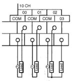
Yes, whatever voltage is needed by the load or output device should be supplied to the output COM which in turn will be delivered to the output terminals when the output is ON.

cpm1a output wiring.jpg
 
thanks Jay

i'm not sure if i can handle this project, i've 2 more months to learn PLC and apply it. i guess i've too much to study, CX programmer, CX protocal, CX designer, etc, all these are new to me, there are so many books and manuals...is it possible for me to complete this project...in 2 months? i hesitate...

anyway, thanks for your reply, jay.i might need to come back and ask for help in the future as well ;)
 
Most of our machines here are mid sized, but there are a few occasions that I have a table-top machine with only a few sensors and 2 or 3 solenoid valves.
I this situation I can get away with no external power supply. I use the power from the PLC output terminals to power the sensors and purchase my solenoid valves with 120VAC coils, and select the relay type outputs. I wasn't my design, I simply inherited it, it works, so why re-invent it. Keep in mind Relay contacts are subject to wear and tear.
However, when in doubt, use an external power supply. Then you can purchase a DC powered CPM. It has the same footprint but is about an inch shorter in height (No internal rectifier circuit). PULS sells a small switching power supply that is din-rail mountable (as is the CPM series PLC), requires no tools at all, and runs very cool. (I think AB now sells the same thing private labelled, but at AB prices)
Check out the PULS mini-line series. www.powermation.com sells them at a great price.
As for the networking stuff, I dunno. Maybe Two higher level PLCs and and several lower-level CPM1a's. Maybe group some of the I/O into larger micro plc's (maybe four 20pt PLCs instead of eight 10pt)
Note that the CPM2 series has a built in RS232 port. Very handy in a micro PLC.
Call up Omron Tech support at 800-55-OMRON. They can walk you through that stuff.


Also, any good vendor should be able to provide some decent start-up to get you going.
 

Similar Topics

Hi dear . I have a system with cj1m cpu11 etn. previously NT 5z HMI was connected with plc. recently my old HMI got damaged. I want to replace it...
Replies
12
Views
226
hi dear all hope you all are fine I have a problem with my CJ1M cpu11 ETN. it stop communication with PC over ethernet. ETN unit all indications...
Replies
4
Views
163
Hello everyone. I am new when it comes to Omron PLCs. Currently I'm uploading program from CJ1M PLC using CS1W-CIF31 cable only. I connected the...
Replies
2
Views
154
Hello everyone. Is the PLC CJ1M CPU13 capable of online editing? Or only downloads that will stop the PLC? Thank you.
Replies
3
Views
341
i have been trying to connect to omron cj1m via peripheral port(USB to Serial), but there isn't any sign to show that it has connected, so am...
Replies
0
Views
317
Back
Top Bottom