GX developer/Mitsi-Q...fan on/off is jittery at setpoint...

Mas01

Member
Join Date
Oct 2020
Location
Leicester, England
Posts
1,105
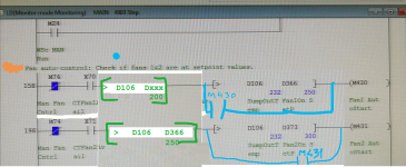
We've got 2 cooling fans on our system. They switch on based on water temperature. One switches on at 25c. The other switches on at 30c. The code works okay, but I noticed that the fans are switching on/off and jittering due to slight fluctuations in water temperature at/near the setpoint values. I want to add some sort of "deadband"/debounce to stop the jitter. I was thinking of 5 Celsius below the setpoint to switch the fans off.
To do this:
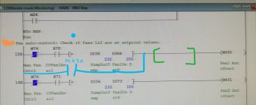
In the green brackets I was going to put:
[> D106 D366 - K5 ]
And also add M430 as shown by the blue line.

I'm not sure if D366-K5 will be recognised or if I need to create another D-register equal to D366 minus 5.

Does this logic look correct? Thanks
IMG_20220712_200529.jpg
 
Not quite, assume fans switch on at above say 25 Deg C then they will switch off at 24.9 at the moment if you use 5 as the compare then it will never switch off, what you need to do is subtract 5 from the set-point i.e. [SUB D366 K5 Dxxx] where Dxxx is a spare register, then use that i.e. [> D106 Dxxx]
the reset is as you have posted i.e. or the M430 round as you already have indicated.
So when the temperature is below set point fans not on, when temperature goes above set point i.e. 25 then the fan switches on & latches with M430, if the actual temperature falls below 25 minus the 5 i.e. 20 Degrees then the fans switch off.
 
I am pretty sure you will need a new D register to hold the lower cutoff setpoint (200 for 20°C for M430; you can use D366=250=25°C for M431).

You were pretty close, but the Manual and Fan-Available booleans would be bypassed once a fan comes on if the seal-in goes all the way to the left rail.

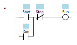
This is the canonical Start/Stop Circuit pattern (cf. here; State/Fault pattern would also work), see below.

In this Start/Stop implementation:

  • the [> MeasuredTemp HiSetpoint*] instruction is the [Start] element;
  • the [M430] instruction is the [Run/Seal-in] element;
  • the [[not-Manual] AND [Available] AND [> MeasuredTemp LoSetpoint]] combination is the [(not-)Stop] element.
* HiSetpoint is D266/250/25°C for M430; LoSetpoint is Dxxx/200/20°C for M430

The purpose of the Start/Stop circuit is to provide hysteresis control in the region between where the [Start] element transitions between False and True and the [Stop] element transitions between True and False, such that the controlled behavior is dependent on from which side of the region the process enters that region: if the process enters the region from the hot side by cooling from 25°C+ to 25°C- with the fan running, then leave the fan running; if the process enters the region from the cold side by warming from 25°C- to 25°C+ with the fan not running, then leave the fan not running.
IMG_20220712_200529.png
 
Last edited:
Also remember that this is ok providing someone cannot enter a very low set point i.e. 3 (30) this then would give a minus figure, either the HMI field should have min/max limits or you may need to do a compare of the set point so for example [> D366 K150]====[SUB D366 K50 Dxxx]
but I assume some checks are in place on the HMI entry field.

Good point. I remember asking in another thread about how to limit inputs on the HMI (GT designer 3), so I know how to do that now. Cheers
 
Last edited:
Brian is correct, do not OR the seal in contact round the Enable signals i.e. M74/X70 & M74/X71 or if the operator disables the pumps they will not stop until the temperature has fallen to the lower limit.
 
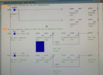
UPDATE: I've changed the code as shown below. I wasn't sure how to use SUB - I kept getting a warning when performing a check. In the end I just used the minus sign which seems to work. Thanks for your help.

IMG_20220713_095359.jpg
 
As a quick look, it seems fine. Yes use the minus sign, I'm so used to FBD where there are both - & SUB both do the same job but the SUB functions have two types SUB (no enable) & SUB_E with enable i.e. in-line. sorry for that.
 
Last edited:
I agree with @parky.

As a style comment, you might consider reversing the order of the ANDed sections (HiTemp/Seal-in => LoTemp => Manual => Available).

It does not change anything functionally, but it "looks" more like the "canonical" Start/Stop circuit (below), which may help someone doing diagnostics recognize it as such in the future. That said, "canonical" is in the eye of the beholder; I have seen the start/seal-in placed on the right.
Start-Stop-Circuit.png
[Source: https://www.contactandcoil.com/patterns-of-ladder-logic-programming/startstop-circuit/]
 
I agree with @parky.

As a style comment, you might consider reversing the order of the ANDed sections (HiTemp/Seal-in => LoTemp => Manual => Available).

It does not change anything functionally, but it "looks" more like the "canonical" Start/Stop circuit (below), which may help someone doing diagnostics recognize it as such in the future. That said, "canonical" is in the eye of the beholder; I have seen the start/seal-in placed on the right.

Good suggestion, I like it.

On the subject of style, when I inherited the code, there were very few comments in it, which was bad news for me as a complete novice. I've since added lots of comments to help with understanding the code. Some people don't like comments or don't see the need for them, I'm the opposite.
 
Last edited:
Yes it is good practice when I used to teach up and coming students we referred to it as the pyramid, hence it's shape, although it makes no difference it becomes easier to monitor & decipher, well at least in my brain, however, this often gets muddled, when on-site & under pressure often a quick on-line change means it is often not followed, spoke to many about this & the consensus is that's fine when doing it in the office with time to sort it but in the field, mistakes can be made, perhaps the quickie mod was to get it going & may not see that bit of logic run for some time so if it works, it may be messy but I do understand when commissioning tidying up can be difficult, did some contracting work where their office based engineers rarely went on-site, they had field engineers to do the commissioning, the office programmers would kick & scream trying to drag them on site, always complained about the site engineers untidy mods etc. but until you have been on a site where the project is running into injury time, the production manager is on your back you do not have time to re-do, It is rare to be able to re-visit & partly or wholly re-write but a great feeling when you do.
 
UPDATE: new logic was tried out in anger today...

OPERATOR: Hey Mas, did you change the logic to stop the fans jittering?
ME: Yes.
OPERATOR: Well, whatever you did, the fans are not coming on when they should be.
ME: Are you sure it's the code?
OPERATOR: Well it worked before the change, So it must be the code.


Turned out the fan's power supply needed resetting after a power outage we had the night before. Once the button was reset, power to the fans was restored and hey presto, the code worked.
 
Last edited:

Similar Topics

Hello I'm new to the forum. I have had experience with PLC's on a small scale for a few years now. I have mainly worked on FX1N series but...
Replies
2
Views
1,613
Hi Been a long time since i programmed a mitsi, last time was the new fx series with medoc! Now i have GX developer and can spend a few days...
Replies
19
Views
12,316
Well, I've decided to start a new project, and like all projects, it has already gone horribly wrong. I purchased a PLC device (supposedly a...
Replies
2
Views
109
Does anybody have any samples of how to "Create and Use" UDT's in CCW Developer Edition? (I am using v22) I can't find any information from...
Replies
3
Views
307
I'm trying to manually convert a Beijer E200 HMI project onto to a new Mitsubishi GOT gs2107-wtbd. The PLC is a very old A-series AS1CPU and is...
Replies
1
Views
380
Back
Top Bottom