Looking for any information or ideas on drawing sets that have multiple control panels on them.
Where I currently work we typically only have 1 panel for 1 machine. However, we have been landing some larger jobs lately that have multiple panels. On the first couple there were only 2-3 panels, but I’m now looking at a job with 8+ panels and things are getting a little hairy.
I know the IEC drawing style uses the function(=), location (+), product(-) but I don’t see anything similar on NFPA drawing styles. Every set I have seen has 100+ pages with all the panels squished into one drawing set. I can see some pros and cons for each way of doing it, but I want to make sure an electrician or contractor can understand the drawing set during install; and I doubt many of them will be familiar with the IEC nomenclature.
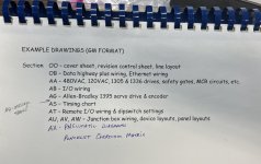
My thinking is that I will have an overall drawing set that will include a list of all the panels, locations, voltage supplies, ampere drawings, etc. I’m thinking of also including a single line diagram, interconnection diagrams, a network layout / list of IP addresses, and a sequence of operations.
Then, I plan to make a separate schematic set for each panel. These schematic sets will be referenced on the main drawing set and will have a file-name designation to separate it from the others (i.e. -EN1, -EN2, etc). I believe this would be easier in the end because each panel will have it’s own set of drawings inside the panel, and the contractor and/or plant personnel can just reference the top-level drawing set that lists all of the panels and connections.
As for wiring between the panels, I was planning to have a dual ID label similar to EN1:1141 / EN2:1155 (This would mean enclosure 1 is landed on wire/terminal 1141 and enclosure 2 on wire/terminal 1155)
Any thoughts on this? Thanks in advance.
Last edited:


