Discrete PID controller simulation

Steven01

Member
Join Date
Oct 2015
Location
Prague
Posts
25
Hello,

I have been developing a library of function blocks. One of the developed function blocks is the PID controller. I have created a Simulink block based on the S-function written in C language to be able to analyze behavior of my implementation of the PID controller.

Here is my C code which I have inserted into the text field in the Outputs tab in the S-function Builder

Code:
double  tmp; // temporary control value
double        satU;
double        dup; // increment of proportional part
double        dui; // increment of integral part
double        dud; // increment of derivative part
double        du;  // increment of control value
dup = Kp[0]*(xD[0] - xD[1]);                        // dup(k) = Kp*[e(k) - e(k-1)]
dui = (Kp[0]*T[0])/(2*Ti[0])*(xD[0] + xD[1]);       // dui(k)=(Kp*T)/(2*Ti)*[e(k) + e(k-1)]
dud = (Kp[0]*Td[0])/T[0]*(xD[0] - 2*xD[1] + xD[2]); // dud(k) = (Kp*Td)/T*[e(k) - 2*e(k-1) + e(k-2)]
du  = dup + dui + dud;                              // du(k)
tmp = xD[3] + du;                                   // u(k) = u(k-1) + du(k)
 
// antiwind-up
if(tmp > Umax[0]){
    satU = Umax[0];
}else if(tmp < Umin[0]){
    satU = Umin[0];
}else{
    satU = tmp;
}
y0[0] = satU;
Here is the C code which I have inserted into the text field in the Discrete Update tab in the S-function Builder

Code:
xD[0] = u0[0] - u1[0]; // e(k) = sp - cv 
xD[2] = xD[1];               // e(k-2) = e(k-1)
xD[1] = xD[0];               // e(k-1) = e(k)
xD[3] = u2[0];               // bumpless transition: u(k-1) = tr
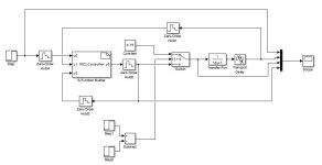
I have prepared following control loop in Simulink (please see the attached figure). The controller controls FOPDT system with transfer function F(s) = 1/(10*s + 1) and transport delay Tdelay = 4 seconds. Parameters of the
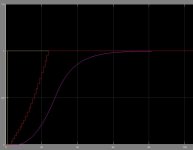
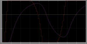
PID controller are set in following manner: Kp = 3, Ti = 8, Td = 2. It is worthwile to say that the control value of the PID controlleris saturated in range <0, 1.5>. I have chosen sampling period T = 1 second in respect to the system time constant tau = 10 seconds (the sampling period is used by the PID algorithm and also by the ZOH blocks). For simulation output (without switching between controller output and manually set control value) please see the attached figure.
The controlled variable oscillates and I don't understand why. The same setting of the controller behaves correctly in analog case with PID controller block from Simulink library. I have tried smaler sampling period values but results are same. Can anybody give me an advicewhat I am doing wrong?
Output.JPG Control_loop.JPG
 
Last edited:
Hello,

I have been developing a library of function blocks. One of the developed function blocks is the PID controller. I have created a Simulink block based on the S-function written in C language to be able to analyze behavior of my implementation of the PID controller.

Here is my C code which I have inserted into the text field in the Outputs tab in the S-function Builder

Code:
double  tmp; // temporary control value
double        satU;
double        dup; // increment of proportional part
double        dui; // increment of integral part
double        dud; // increment of derivative part
double        du;  // increment of control value
dup = Kp[0]*(xD[0] - xD[1]);                        // dup(k) = Kp*[e(k) - e(k-1)]
dui = (Kp[0]*T[0])/(2*Ti[0])*(xD[0] + xD[1]);       // dui(k)=(Kp*T)/(2*Ti)*[e(k) + e(k-1)]
dud = (Kp[0]*Td[0])/T[0]*(xD[0] - 2*xD[1] + xD[2]); // dud(k) = (Kp*Td)/T*[e(k) - 2*e(k-1) + e(k-2)]
du  = dup + dui + dud;                              // du(k)
tmp = xD[3] + du;                                   // u(k) = u(k-1) + du(k)
 
// antiwind-up
if(tmp > Umax[0]){
    satU = Umax[0];
}else if(tmp < Umin[0]){
    satU = Umin[0];
}else{
    satU = tmp;
}
y0[0] = satU;
Here is the C code which I have inserted into the text field in the Discrete Update tab in the S-function Builder

Code:
xD[0] = u0[0] - u1[0]; // e(k) = sp - cv 
xD[2] = xD[1];               // e(k-2) = e(k-1)
xD[1] = xD[0];               // e(k-1) = e(k)
xD[3] = u2[0];               // bumpless transition: u(k-1) = tr
I have prepared following control loop in Simulink (please see the attached figure). The controller controls FOPDT system with transfer function F(s) = 1/(10*s + 1) and transport delay Tdelay = 4 seconds.
At first glance I say your gain is too high.
I plugged your open loop transfer function 1*exp(-4*s)/(10*s+1) into my simulator and I get a nice result but my controller gain is much lower Kp=0.438 %control output/unit of error, Ti=0.233 min Td = 0.048 min


Parameters of the
PID controller are set in following manner: Kp = 3, Ti = 8, Td = 2. It is worthwile to say that the control value of the PID controlleris saturated in range <0, 1.5>.
Usually the time constants are expressed in minutes for FOPDT systems.
Why is the control output limited to 0 to 1.5? Usually the control output has limits of 0 to 100% or -100% to 100%.

I have chosen sampling period T = 1 second in respect to the system time constant tau = 10 seconds (the sampling period is used by the PID algorithm and also by the ZOH blocks). For simulation output (without switching between controller output and manually set control value) please see the attached figure.
One second sampling is is good.

The controlled variable oscillates and I don't understand why. The same setting of the controller behaves correctly in analog case with PID controller block from Simulink library. I have tried smaler sampling period values but results are same. Can anybody give me an advicewhat I am doing wrong?
You must get the units straight.

How did you calculate Kp=3, Ti=8 Td=2?

Let's change the problem a bit to make it more realistic. Use the same open loop transfer function but assume it is for temperature control. Assume the ambient temperature is 25 degrees C. K is the open loop gain which has units of 1 degree/%control. The time constants and dead time are in minutes so the plant time constant is 10/60 minutes and the dead time is 4/60 minutes. Now the controller can be a proper ISA controller.

Start the initial temperature at ambient temperature or 25 degrees C then change the set point to 100 degrees C. The set point should be reached in about 3 minutes.

The steady state control output should be 75% because the temperature is increased 75 degrees from ambient and the open loop gain K is 1 degree/%control.
 
Peter, thank you for your reaction. The controlled FOPDT system along with the PID controller setting comes from the book Practical PID Control page 35-36 (there were no units for PID controller parameters). According to the notes these values were determined based on the Ziegler-Nichols tuning rules. The idea behind this was that I use plant with appropriatelly tuned PID controller (its analog prototype) and verify my PID controller implementation. I supposed that I can use the tuned parameters for analog case and only convert them into their discrete counterparts.

As soon as I tried the values you suggested along with the controller output limits set to <0, 1> I received much better behavior (please see the attachment).

What I still don't understand is why the idea with converting the parameters for the analog PID controller into their discrete counterparts doesn't work.

Output_02.JPG
 
Last edited:
I don't see anything wrong with your code as shown above. Only the values for K, Ti and Td seem off.

Maybe this will help
In this example there is an extreme long dead time so I used a Pade approximation for the dead time. You can see it worked well. All the derivation, math and results are shown.
https://deltamotion.com/peter/Mathcad/FOPDT/Mathcad - FOPDT PID.pdf
You should also look at my YouTube channel 'Peter Ponders PID'

Time for a little rant.
When anybody suggests using Ziegler-Nichols you should ignore their advice. There are better methods for tuning systems. ZN tuning will overshoot.

Too many text books are written by people that have no practical experience. These authors simply repeat what other fools have said before.

Matlab and Simulink are good for getting answers, but not so good for providing understanding.
 
Originally posted by Steven01:

As soon as I tried the values you suggested along with the controller output limits set to <0, 1> I received much better behavior (please see the attachment).

I'm not sure I agree with that. The controller is in saturation and the process variable is simply settling at the level it would reach with an open loop output of 100%. You aren't in control. You are in steady state open loop equilibrium. Try a setpoint of 1/2 the setpoint in the example you show and see what it does with that.

Keith
 
I have decided to evaluate behavior of the PID controller algorithm directly on
the target hardware. I simulate controlled plant i.e. FOPDT by the digital first order
low pass filter in cascade with a delay line (implemented as a circular buffer).
The PID control algorithm is executed along with the plant emulator in the same
task with execution period equaled to 10 miliseconds (chosen arbitrarily). I have
used the same PID setting as in the Simulink simulation i.e. Kp = 3.0, Ti = 8.0,
Td = 2.0, Umin = 0, Umax = 1.5.

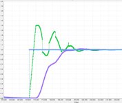
This simulation gives different results (please see the attached picture where
meaning of individual waveforms is following:

blue - reference signal
green - controller output
purple - controlled value)

I am confused because of I have received different results than the Simulink has
offered. I don't know what shall I trust. Do you think that the idea with the PID
controller and plant emulator executed in the same task is correct?

Real_time_simulation.JPG
 
The execution rate does not need to be that fast. 1 second is fast enough. I used 1 second in my example below.

Do you think that the idea with the PID
controller and plant emulator executed in the same task is correct?
Yes! This way you are sure that the both have the same time base or update interval.

I see NO justification for your controller gains. The controller gain and time constants look like they were chosen by a human guessing or using trial and error.

I have updated an old Mathcad worksheet I did when I was contributing to the www.controlguru.com site back in 2005. I used the same model as Steven01 did but it did it in a more realistic way. I also DERIVE the controller gains based on the the the provided transfer function.
I should have changed the PID controller to a I-PD controller so there would be no "derivative kick".

BTW, I see no evidence of the "derivative kick" in Steven01's example yet he claims to be using a PID.
 
I think your code is misordered.
Code:
xD[0] = u0[0] - u1[0]; // e(k) = sp - cv 
xD[2] = xD[1];               // e(k-2) = e(k-1)
xD[1] = xD[0];               // e(k-1) = e(k)
xD[3] = u2[0];               // bumpless transition: u(k-1) = tr
You are updating your xD[0] before you have stored the previous xD[0] in xD[1].
This will ruin your PID algo, as proportional change will always be zero, integral will be ok, derivative is acting like what you want proportional to be doing.
Let me know if that fixes things (I think move the first line to the last line)
 

Similar Topics

Hello, I have already searched for that in the forum but did not get any satisfying answer, so here it goes: I have a 1769-L36ERM that controls...
Replies
4
Views
3,109
I'd appreciate hearing opinions and experiences of going from discrete controllers to PLC control of temperature. We use a lot of Watlow and...
Replies
12
Views
5,984
Does anyone have any examples of how to control a temperature of a PID loop that is firing a discrete output for logix 5000? Any help would be...
Replies
4
Views
2,616
I have been assigned a project where I need to use a PID in a PLC5/80E to control the temperature of a chemical in a tank. The chemical goes...
Replies
3
Views
4,746
Gentlemen, I'm faced with controlling a valve that has 480 feed to it, but using 120Vac On..Off discrete signals to position it. It does have...
Replies
8
Views
3,759
Back
Top Bottom