Siemens L Stack, OB35

Rob...

Lifetime Supporting Member
Join Date
Jul 2016
Location
Manchester
Posts
483
Ok, curiosity has gotten the better of me.

I have some code I'm working on written by others, an I've spotted this. I am not sure the reasoning behind it aside from trying to make the software as hard as possible to follow. (Which the rest of it, whoever has written it seems to have tried to do).

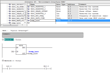
So I've created a dummy OB35 to show you a picture of what I am curious about. It isn't the actual software but basically doing the same thing.

Input byte 2 is moved into a temporary byte in the beginning of OB35 (called every 10ms).

Later in OB35 the first bit of the byte is accessed utilizing the L stack L20.0.

Is there any reason for doing this and not just simply using I2.0 and removing the move instruction. (No other bits in the byte, or the #temp_byte are used anywhere else).
Lstack.png
 
I honestly don't see how it would be different than just using I2.0. I'm curious if anyone has an answer for this as well.
 
Reuse of OB's? OB35 is one of the timed OB's and as such can have more than one copy in the same PLC with a separate number.

Changing the first network is easier than changing all networks... although, this is a flimsy at best excuse, but the only I can think of.
 
I was thinking doing it like this would ensure true representation of I2.0's status at the beginning of scanning OB35.

However, Siemens doesn't scan in a way that this would have an effect? Or would it?

There is code all over the show similar in fashion. (Not always using L stack, but convoluted). An I'm sure used only to stop people cross referencing, or to mess the machine up if someone who doesn't know the code intimately makes a change.
 
I should add, I know it can be used for some quite good things. I was always taught bad practice to use the L stack in this method.

An if it was for a timing issue etc.. why not move I2.0 into #temp_bool an then use #temp_bool etc...
 
Weird, Normally if you need to access inputs in an interrupt then you need to update the input byte/word in the OB. I.E. in interrupt OB then L PW 0 T IW0
Direct access to inputs/ outputs cannot be done by using I & Q areas as these are updated cyclically in the scan Peripheral Bytes/words are the real time I/O.
 
We also practice this for OB35 where i work.

The reason simply beeing;

If you have a homing sensor on a servo drive, most drive takes the input from the homing sensor directly on one of the drive input terminals. With the size of the machinery that we do, that would easily force us to have 50-100 meters of cable for every single homing sensor.

Instead, we use normal decentral IO like the ET200SP and wire the homing sensor to these.
Another deceltral IO located in the main panel together with the servo drives, will then set an output, which is connected to the input of a servo drive.

To achieve the smallest latency we use OB35, which in our case is set to 5ms interrupt.

Since you are not able to access a single input bit on the periphial, we copy the whole input byte from the periphial.
The local byte you are able to access by bit level, and so the input from the homing sensor can through the local byte etc L20.2 set the output Q50.0

In the end of OB35 we will move QB50 to PQB50 to update the output byte right away.


Simply, this is a software fix for a hardware money saving issue.
 
Last edited:
The move in the posters code is using IB2, not PIB2


As already posted, you would load PIB2 and transfer it to IB2 and then use I2.0 in the code for your type of system.
 
I realize that it is IB2 that is used in the posters picture, and that is probably a mistake made by the creator of the program.
But he seemd to also be curious whether why and when this kind of practice is done, so i gave an example.

It was not to offend anyone.

Furthermore i do not recommend moving the PIB into the IB.

If your normal scantime is 10ms and your OB35 scantime is 5ms, you could end up in a situation where in the first half of the cyclic scan your inputs are 0 and the other half scan it would be changed to 1.

It is a very theoretical point of view, yes i know.
But it is true, and could in extreme situations cause faults that are very hard to troubleshoot.
 
Just to clarify. I did not write the original code, an there was no mistake in me using IB instead of PIB.

I understand how PIB works, was my curiosity that couldnt think of a reason behind someone writing it this way.

Maybe just an error on their part, maybe he was just being a jackass an making life difficult for following people.

What the original code is doing is simply counting revolutions of a machine, probably 6-8rpm max. An then working out some distances in the range of 180 - 270 m/min. So hardly even so time critical.
 
Just to clarify. I did not write the original code, an there was no mistake in me using IB instead of PIB.


Sounds like that original programmer have mixed meaning of IB and PIB addressing on siemens PLC and interrupts.


Ix and PIx meaning are often mixed :ROFLMAO:
 
Could the program have been migrated from a PLC with asynchronously updated I/O?

I think originally this machine was controlled with Step 5.

I've not much knowledge on that platform.

However, the conversions I've worked on in the past, this software would've been almost completely re written if it was an upgrade.
 
I think it was probably S5, however I assume that the original programmer made a mistake thinking IB would update instantly, I have seen this before. S5 Definitely only updated the Inputs at outside the OB1 scan, the interrupt had to be used to update the inputs/outputs. I have seen other ways of doing it as well for example one program I came across they created an FB that updated the input Image and called this many times in OB1 in between calls to other blocks it worked but probably on a wing & a prayer.
If the code above works then it is probably because the update of the inputs outside of the PLC scan is fast enough to catch what ever it requires or it is not that important. I suggest that the code be modified to actually update the image i.e. L PIB T MBxx (suggest use a flag byte), however Siemens stated that in S5 the proper way was to update the input image.
 

Similar Topics

The past week we received a new piece of equipment from Germany which utilizes siemens controls. Typically in our company we use A.B. controls for...
Replies
4
Views
42
Hello I have a s7-1200 and I would like to read the tags present in this controller with my controllogix controller. The two controllers don't use...
Replies
5
Views
102
Hi need help why this “failure 5 emergency stop “ appears at every startup in the morning ? Have to shut off main switch at least 10 times on...
Replies
19
Views
282
i have two plc 1. s7-1212dc/dc/dc ip; 192.168.0.1 2. s7-1500 1513-1pn ip; 192.168.3.2 i need to get data from plc1 to plc2. any idea how to do...
Replies
5
Views
97
Hi everyone hope you'll well. Is it possible for me to download a Crack version of tia portal v13..sorry to say this but the software is very...
Replies
5
Views
196
Back
Top Bottom