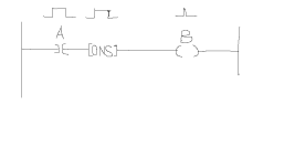
need help with ons instruction

mike3475

Member
Join Date
Feb 2013
Location
brooklyn ,NY
Posts
334
good day everyone!
i had issue with ons instruction, with drawing i attached:
we checked with trend waveform, the A waveform and ONS waveform are always present, but B waveform int missing.
anyone knows why?
thanks!

ons instruction issue.png
 
it's PROBABLY too fast/quick to see on any "waveform" that you're using ...

TIP: put a simple ADD instruction in place of the OTE ...

use a new DINT tag (example: X) for Source A ...

use the value 1 for Source B ...

use the same new tag (X again) for the Destination ...

now try your test again and see if the value of X is incremented each time you fire the rung ...
 
You mentioned "A" is always present. You must have the rung condition go to false before a one shot will reset. It will only "pulse" once, hence the name one shot, then the power to it ("A") needs to go off for a scan cycle. Ron has a great idea about using the "ADD" instruction. If it does not increment, then toggle the bit "A" and see if it will then. That's when you'll know that you need to look at "A" to get it to cycle. Hope this helps.
 
Assuming you are using Logix5000, did you use the proper tag for the ONS? When i took a class in college i could never understand how to address them properly.
 
Mike, yes Pumba makes a very good point. I always make my one shots a BOOL[32], like an array, so I can have each one shot a different tag, otherwise they'll all fire at once. I did a large program where we had over 160 one shots, each with it's own tag.
 
One way of testing if B ever comes on is to:

XIC B ------- OTL C

If B does come on C will latch on.

I do this frequently to see if something is being active or scanned when troubleshooting.
 
One way of testing if B ever comes on is to:

XIC B ------- OTL C

If B does come on C will latch on.

I do this frequently to see if something is being active or scanned when troubleshooting.

I think if you'll give the "ADD" approach a try you'll like it better ...

yes, the OTL will tell you that the code has been executed "at least once" with TRUE logic - but the ADD has the advantage of telling you HOW MANY TIMES the TRUE execution occurred - and usually even more important - whether or not the TRUE execution is still continuing scan after scan ...

plus - the ADD approach will let you easily spot a continuously TRUE logic execution at a glance ... the OTL approach on the other hand, has to be toggled back OFF after each test - before you can trust it to "trigger" ON again for the next test ...
 
Last edited:
I am sorry for late reply.
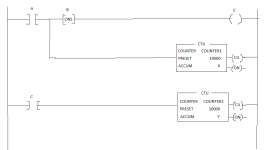
This is real existing PLC issue. I did test it with CTU instruction to count numbers, I found the number X is bigger than the number Y after reset both counters.
Thanks everyone!

Modification.png
 
so - did you find your problem? ...

TIP: in the future, be careful with using "Counter" instructions for this type of troubleshooting ... the CTU instruction has a CU (Count Up) bit which can confuse your analysis ... in particular, the CU bit will be written to a ONE condition (by the PRESCAN operation) whenever the processor has a "Go-To-Run" experience ... using the ADD instruction will often give you more reliable test results - since the ADD doesn't have a CU bit ...

note that in your latest figure, if you leave input A ON/TRUE - then your Counter1 will give you a "false count" of ONE whenever you do a RES (Reset) command ... this is because the RES instruction will "reset" the CU bit - as well as the CTU's Accumulator ... this could be VERY confusing when you're trying to troubleshoot certain types of "scan-related" problems ...

hope you got it fixed ... good luck with your project ...
 
Last edited:

Similar Topics

Hello guys, PLC 5 guy here who recently took a course through automationtraining.ca for some basic understanding on how to navigate through...
Replies
4
Views
2,352
Hello men Hardware: PV Plus 1000 1769-L32E Proccessor 1769 I/O Stratix Unmannaged Switch I am trying to upload a project named "test_1" to...
Replies
18
Views
8,440
Hello I am new to setting up communications between my PC and my 1769 L32E proccessor. I have been trying to figure this out but no cigar...
Replies
5
Views
4,793
Hey guys Hardware: 1769-L32E CPU 1769-PA4 Power Supply 1769-IA16 Input Card 1769-OW16 Output Card 1769-IF4XOF2 Analog Card I just built a PLC...
Replies
14
Views
4,394
A ___ A ____ is defined as the end-point in the conversation, which can be a client interface in executable or Web script form,or a programmed...
Replies
3
Views
1,811
Back
Top Bottom