SLC 5/05 programming question

mtech2766

Member
Join Date
Jun 2021
Location
Indiana
Posts
20
I am just finishing up my project, which was my first experience with PLCs. I thank everyone that has helped me work through the RIO and analog scaling problems.

I am checking to make sure the ladder diagram is documented correctly, and am having a problem with the 24 Vdc discrete input symbols.

Each of the discrete Inputs have a different description, but the Symbol listed on each is something I don't recognize, but I can't seem to change it.

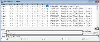
The symbol is RAW KV.0/0
RAW KV is present in my program, it is an Analog Input (not digital), but 0/0? Each of the bits of have a different description.

How do I change the 'symbol' shown?

Thanks.
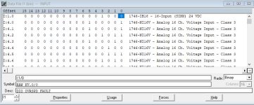
PLC Input Symbol.JPG
 
That symbol name doesn't make sense to me. It has a space and a period. Neither are allowed. No spaces, no special characters other than an underscore. You say it is analog, but the I/O config shows a digital card. That worries me. I'm worried that your RAW_KV symbol is tied to the wrong address. If you click on I:1.0 you should be able to see the symbol assigned to the entire word. You can remove it or change it from that window.

I can see RAW_KV (with an underscore) being used, and it being assigned to I:1.0. Then bit 0 would automatically be RAW_KV/0. But then you could just click on that bit to change the symbol for that one bit. But as you said, RAW_KV probably should be tied to an analog signal, not the digital module.

You should be able to just click on the symbol name and enter a new name.

OG
 
Last edited:
Look clear to me

I:1 is an 24VDC digital input locatd in slot 1 bits 0-15 = Inputs 0-15

I:4.0 through I:4.15

I4: is a 16 Channel analog input module located in slot 4
words 0 - 15 are the analog values
both can be repesented as 16 bit integer standard programing
the data table shown is the data table in the PLC processor the values the program has access to
if you want to change the symbol select the bit and change it
in the SLC's the symbls are in a seperate file that is only in the programming computer
 
I selected the bit, selected the symbol field - pic 1
deleted the info - pic 2
closed and re-opened the window - pic 3

In fact, if I click on a different window the computer, the RAW KV.0/0 re-appears.

I am using I:1.0 - 15 as 24V digital inputs.

The Raw KV is a description I had for I:4 analog input, but changed it.

Does it matter that I am not actually connected to the PLC? I wouldn't think so.

pic 1.JPG pic 2.JPG pic 3.JPG
 
I selected the bit, selected the symbol field - pic 1
deleted the info - pic 2
closed and re-opened the window - pic 3

In fact, if I click on a different window the computer, the RAW KV.0/0 re-appears.
Sounds like the symbol is attached to the word. I don't have 500 handy to check atm, but iirc if you have a symbol/description on a word it will pass through to any blank symbol/description on the individual bits.

EDIT: To check, do what the poster above me said and delete the symbol there :)
 
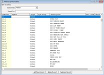
okay, I figured that out by openeing the Address/ Symbol Editor.
the RAW KV symbol was located where my cursor is.

But now I see another issue: All of my I:1/1 - I1/11 are duplicated as I:1.1 - I:1.11
Is this just a text file?
Is this a problem?

thanks

editor.JPG
 
Those are not duplicates. I:1.1 etc are other words, the actual hardware for which may not exist in your current setup (or rather certainly do not given I:1 is a digital input card which only uses a single word).

The offline symbol/description database is not limited to only storing data for actually used addresses. It sounds like you somehow may have copied your symbols/descriptions from I:4 to I:1 at some point.
 
Last edited:
Yes, I:1/1 is actually I:1.0/1


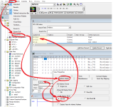
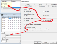
Update - what RSLogix 500 displays depends how the Address Display is configured for I/O; see below.

xxx.png

yyy.png
 
Last edited:
I got dizzy just looking at that graphic!

If you have a symbol attached to the entire word I:1.0 then the symbol is passed-through to each individual bit.

For example, let's say I:1.0 has a symbol "Conveyor". You would then have I:1/0 (also I:1.0/0) with the symbol "Conveyor/0".

If you clicked on that symbol and typed in a different name, then the system would use your new symbol. If, however you simply erased the symbol, the passed-through symbol would just come back.

OG
 
Last edited:
I got dizzy just looking at that graphic!

If you have a symbol attached to the entire word I:1.0 then the symbol is passed-through to each individual bit.

For example, let's say I:1.0 has a symbol "Conveyor". You would then have I:1/0 (also I:1.0/0) with the symbol "Conveyor/0".

If you clicked on that symbol and typed in a different name, then the system would use your new symbol. If, however you simply erased the symbol, the passed-through symbol would just come back.

OG


Exactly.
 

Similar Topics

I have a floating point value (F12:0) that I need to copy to three 3 digit integer addresses (N12:0-N12:2). I don't need the decimal portion...
Replies
8
Views
3,126
Hello, I've taken on yet another basket case old machine running an 7 slot SLC 5/03 PLC.... I have run into a situation where I see the same 4...
Replies
3
Views
5,619
Hello guys. Got Slc5/04 with 9pin d shell port in it. Have cheked some manuals and this port is an RS 232. I want to ask if I could use a generic...
Replies
3
Views
2,351
i have a slc 5/02, but i'm not sure wich software to use (i have both rslogix 500 and 5000) but the main problem is that i dont have the cable, i...
Replies
12
Views
5,699
On site computer is using 1784-PKTX. The computer is connecting to 1785-KA5. I can program the SLC 5/03 with DH+.(1784-PKTX to 1785-KA5 to SLC...
Replies
1
Views
1,740
Back
Top Bottom