Guide me, how to 'simulate' and SLC500 in the PLC.

JesperMP

Lifetime Supporting Member + Moderator
Join Date
Feb 2003
Location
ᚴᚬᛒᛅᚾᚼᚬᚠᚾ
Posts
16,323
Hi.

I have a legacy project with an SLC500 PLC (SLC5/04 CPU), and we want to connect a data logging system to it.
Management want to make a test offsite before implementing it onsite.
I am a bit rusty, since it is approx. 20 years since I worked with AB SLC500.

We do have SLC5/04 CPUs, Racks and power supplies, but we do not have the exact IO modules.
Correct me if I am wrong, but I think that it is possible to simulate the program in the CPU. For the slots in the rack that are not fitted with the correct IO module you have to disable said slots so that the CPU doesn't fault on hardware error.
I have looked into the system file, and I think that S:11 and S:12 can be used for this purpose. Do I simply set all the bits to TRUE and set the CPU to RUN ?
Anything else to be aware of ?
 
Last edited:
Long time since I used SLC but there is a map of Enable/disable bits you can set to 0 for each I/O module, This effectively ignores the actual I/O, so that you do not need the modules. cannot remember now where this is located but think it's in controller properties, in the past I used to map the real I/O into & out of a binary file & use those bits n the program but disable the calls to the mapped bits & create program files to simulate the inputs, again I cannot remember if you can force the inputs within a program however, then when project complete just re-enable the i/O mapping & change the slot bits back to enable.
I do seem to remember our PICs simulation could write to inputs but it was over 20 odd years ago.

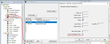
Unsure if this is different from SLC to MicroLogix, but on Micro the "Ignore Configuration Error" option is under IO Configuration > Adv Config (with the I/O module selected) > Ignore Configuration Error (screenshot attached). This obviously has to be selected for each I/O module. I've used this successfully to (partially) bench test MicroLogix 1100 programs with only a processor and none of the required I/O modules.

Again, could be completely different on SLC as the config for modules is often done by writing bits, but I'm not too familiar with that process.

IOConfigError.JPG
 
For the 5/04 you are correct in that S:11 and S:12 would be used to effectively disable the various I/O slots. There is no option in the 5/04 to ignore configuration errors. It is done slot by slot for slots 0 - 30.

S:11/0 - S:11/15 would be slots 00 - 15
S:12/0 - S:12/15 would be slots 16 - 31

Be aware that you do not use bit #0 (S11:0/0) as that would represent slot #0 and the SLC would sit in that slot and has no I/O. That bit would only be disabled on the old brick-style fixed controllers.

Bit #31 (S:12/15) also would not be used since there is no slot #31.

Set a bit to "1" to enable and set the bit to "0" to disable the slot. Be aware when disabling, that data values will be frozen in their last state. They do not automatically turn on or off.

OG
 
Didn't see it mentioned but the rack size will have to match. If the original was in a 7 slot rack it can only be run in a rack with a minimum of 7 slots. In other words if the original program was in a 7 slot rack and all you have is a 13 slot rack then disable all the slots and change it to 13 slot rack. Then it will run.
 
JaxGTO, that was my recollection too but I didn't remember the details.

I know I'd run into it with my little compact 4-slot rack on the test bench, and I recall Jim Hull in SLC explaining to me why he had a 13-slot rack on his bench.
 
So, got around to actually do the test.
It turned out, as it was mentioned by JaxGTO, that the size of the SLC500 rack size in the program must match the rack that the CPU is physically installed in.
So if the program is made for 7-slot, and you are testing in a 13-slot rack, then the program has to be modified to match the 13-slot rack.
And after setting all the slot enable bits to off, the CPU could be switched to run mode.

Thanks again for the assistance.
:site:
 
Resurrecting this thread, since I have had one more project that require me to test a connection to a simulated SLC500.

New information: If the SLC500 program refers to any M0 or M1 addresses, then the CPU will fault when it tries to address the module for the M0 or M1 address that refers to a disabled slot. The only remedy is to delete the rungs that refers to the M0 or M1 addresses.

The information may be helpful to someone.
 

Similar Topics

Hello everyone, I am currently working on a project that uses a Rockwell L33ER controller and the FTV Studio V13 as Supervisory computer...
Replies
0
Views
128
1756-L82ES controller, V33 lastest firmware using a Sick brand encoder to monitor position on the shaft of a conveyor. (call this conveyor) I...
Replies
3
Views
1,197
Hi. :thumb: Has anyone the fanuc CNC Guide installer? full or trial version. thank You.
Replies
0
Views
921
A complete guide to utilize Git in your plant use AssetCentre as a "Build" tool. Hello PLCs.net! I have found my older tutorial to be really...
Replies
1
Views
2,467
Does anyone know of a good guide to locking down Windows workstations in a domain setup, so only specific software (such as your SCADA software)...
Replies
3
Views
1,653
Back
Top Bottom