Studio5000 IB8S COP Instruction

LKHero

Member
Join Date
Dec 2021
Location
Ontario
Posts
2
Long time lurker, first time poster..

I've been working with PLCs for a while now and have ran into a head scratcher that I was hoping someone (smarter than I) could shed some light on for me.

We have a UDT created to map 1734-IB8S cards into the same format as our schematics. This UDT is a series of separate BOOLs that make up the RunMode, ConnectionFaulted, and 0-7 for the Data (status omitted). Making a total of 10 bits in our UDT. The tag created from the hardware has 18 bits.

We then use a COP to try to grab these first 10 bits but the only thing that works is adding an INT between the Connection faulted and the first data point in our UDT.

Is anyone aware of why we would need that dummy INT for this to copy properly? Doesn't seem to line up to me.. I would like to understand WHY it works so I can be confident it is a valid fix.

PLCTalkQ.png
 
Last edited:
A good question. Just to check, is the tag data type for the source element AB:1734_IB8S_Safety2:I:0?

Assuming it is...

Some investigation suggests that there must be either some padding or some data that's simply not available to the user -- the Module-Defined tag has a size of 8 bytes, whereas if it only contains the 18 bits listed it should have the minimum of 4.

As such, based on your successful UDT we can can tell that the RunMode bit is bit 0 of the module data tag's actual internal structure and ConnectionFaulted is bit 1... but the actual data points are bits 0-8 of the second word.

In short, the internal structure of the module tag does not actually match what it shows you; the inserted INT pads out your UDT to line things up with the actual structure.

As an aside, I now have a good guess as to why the machines at my plant map IB8S to our UDTs using individual bits rather than a COP :)

EDIT: Misremembered how Logix aligns INTs in UDTs.
 
Last edited:
It's probably a bit overlay. I would open up the definition and look.

Apparently if I open it in v32 the warning about it containing a bit overlay doesn't pop up. Had to go back to an earlier version to see it.

Doesn't really change anything as it's a Module-Defined data type, but does explain how they managed it.
 
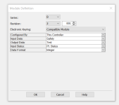
Be aware that the 1734-IB8S module image can have different elements in it by changing its definition. Pull down the "Input Status" for the different options. It could explain the difference you are seeing.

Capture.PNG
 
Yep there is unused and unseen bits inside that module data type. I ended up copying the tag to a temporary array of two INTs then copied [1] to the desired destination udt and it cleaned up all the bits for status mapping.
 
This was great to look back at and see this many responses!
It somewhat satisfies the itch of needing to know why, just missing some details but timelines don't always allow that. We did it the way that forced that .NotAvail to help it along and accepted it as is.

Cheers all.
 
In CLX BOOLs are packed into bits of an integer. This can be seen by building a user defined data type of one BOOL. This UDT has a size of 4-bytes. As you add more BOOLs, the size does not increase until you reach 33 BOOLs. Then, it jumps to 8-bytes. If you examine this UDT by outputting the code in an L5K, you will see the BOOLs are packed into SINT (byte) with a "Hidden = 1" attribute. It takes 4-bytes to make a DINT. The DINT is the base size for all UDTs.

If you look at the 1734_IB8S date type under "Data Types/Module-Defined/AB:1734_IB8S_Safety2:I:0" you will see it has a size of 8-bytes. This is the size your UDT should be. With your definition, your UDT was only 4-bytes. When you added the INT after the first two BOOLs in your UDT, CLX packed the first two BOOLS into the least significant bits of a SINT (least significant byte). Because only two INTs can be packed into a DINT and INT was in use (your SINT), the INT went into the most significant two-bytes. Your remaining BOOLs went into the next DINT (4-SINTs). Thus, making a UDT of 8-bytes total.

If you have started down this path, you will continue to develop it but be aware that you should carefully test to verify the mapping of data from Rockwell's module data types to your UDTs because bits can be mapped into different orders that do not match what you see (assume) in the UDTs. You cannot look into Rockwell's Module-Defined UDTs.

Also remember, that data transfer size in a COP instruction is controlled by the destination variable.
 

Similar Topics

I have an array of 55 REAL values. Is there a way to multiply based on the array location ? I have 55 transfer belts that are equally spaced...
Replies
3
Views
152
Hi Hope you all are doing well. Iam working on a project with some AOI. I also hate no online edits... lol. My problem occurs when I use a UDT...
Replies
2
Views
157
I am not sure if this is possible but if there is a way, you guys would be the ones to know. I am currently working on a project where we are...
Replies
7
Views
216
Hi all. I'm having issues adding an ethernet module to my project in Studio500 v34. The device is a Fredericks Televac EthernetIP MX gateway which...
Replies
8
Views
353
The day of week program started changing day of week 2 hours early. It changes at 10 P.M. instead of 12A.M. Just started this year.
Replies
22
Views
2,660
Back
Top Bottom