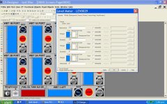
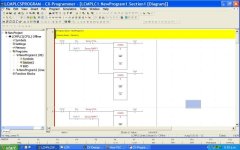
How PLC displays tank levels on touch screen graph.

termus123

Member
Join Date
Dec 2012
Location
New Zealand
Posts
4
Hi, I'm new to PLCs and my boss kind of forced a project on me regarding PLCs.

I am using a OMRON touch screen, CP1L, CP1W-AD041 and a 8BER

Logically the project is very simple, the ship has 8 ballast tanks to balance the ship, there is a switch for fill, a switch for empty and a stop switch for each of the 8 tanks.

I need to get my PLC to display a graph representation 0-100% of the current water level of its designated tank on the touch screen. To measure the water level I'm using a 4-20mA sensor.

On CX-Designer, the interface was a piece of cake to set up, however, the graphs on there I have no idea how to get that working.

The problem is that I've never touched a PLC or seen one in my life so I can't for the life of me figure out what I need to do in CX Programmer to get that graph working or if I even need to program anything? I'm assuming since the analogue sensor 4-20mAs is detecting the water pressure I need to do something in the CX Programmer to translate that into 0-100%? Or is it going to do that automatically? Where do I start?
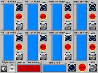
LCMTanksDisplayScreen.jpg
 
The AD041 will produce a value of 0 to 6000 for the 4-20ma input. Those will appear in a CIO address like 002-005 depending on the CP1L model.
If those are Level Meters on your screen you could just scale them 0-6000 and attach them to the CIO address but that only works IF your inputs read 0 when the tank is empty and 6000 if when the tank is full.
 
Hi Mendonsy,

Thank you for your swift reply, the exact model of my CP1L is CP1L-EM30DR-D.

I have checked the spec sheet of AD041 prior to your commend and the resolution is as you say 0-6000.

Those are indeed level meters on the screen, my question is how do I scale those meters to 0-6000 but have it displayed in % and which program do I use to do it with? Because the screenshot was done in CX-Designer but shown in the screen below those are the only options I can find for the graph.

Thank you in advance!

Q2.jpg
 
Probably the easiest solution would be to use the unsigned binary divide instruction (/U) to divide the analog value by 60 and store it in a D register. You can then display the D register directly.
Assuming the data is in 002 your instruction would be something like /U 002 &60 D0.
 
Last edited:
Just to provide some addition information,
the ship currently already has a functional non plc/hmi controlled mechanical system with push buttons but they want to upgrade to plc/hmi so they can see a visual representation of the water levels in their ballast tanks.

The PLC's output goes to a relay and from there on it is no longer in my scope as they will be setting it up.

My scope is to get the digital output out and have the HMI interface shown above working with the graph for the water levels working.
 
Thanks for the suggestion, seems like what I would end up doing.

Regarding the ladder logic for this, displayed is what I've got so far but I'm not sure what I need to input into the CX Programmer to get the Sensor FULL & Sensor EMPTY to automatically switch off @ 100% & 0% respectively. In addition, my boss tells me that there needs to be a digital output at the end which shoots out some binary stuff which from looking at other examples and reading the manual I've just added 2 coils and gave them an address, that output is going to a relay I think.

If anyone can help me out with what I've got so far I would be most grateful.

Thanks in advance.

Q4.jpg
 

Similar Topics

It's that time of year: how are you using PLCs to run your lights or animated displays?
Replies
4
Views
3,041
I am having trouble with a few displays in factory talk SE. I am trying to have specific displays appear when a specific tag is set to a value...
Replies
1
Views
2,494
I have a machine which is undergoing upgradation. As part of the process two SEW drives are being replaced., existing Gen B with new Gen C. The...
Replies
1
Views
63
I was loading a program onto an XE1e2 PLC and it got stuck on these two windows and won't progress. It won't let me connect from the PC to reload...
Replies
0
Views
51
I'm a beginner in the automation field and I've set up an automation system connecting several devices (datalogger, radio, etc.) via Modbus RS485...
Replies
5
Views
174
Back
Top Bottom