Confusion regarding timer in RSLogix5000

Salman S.

Member
Join Date
Oct 2016
Location
Malaysia
Posts
41
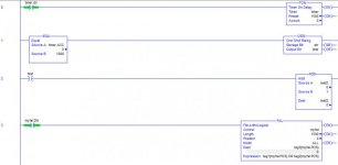
I have this program whereby I perform an activity based on a timer reaching a certain value. This 'activity' occurs every time the timer runs without any issue. However, if I introduce a FAL instruction that ORs 1000+ times in that routine, the activity fails to occur majority of the time. Reducing the length, improves reliability of my activity (occurs closer to the rate of the timer). Also, the average scan time is very low (10ms or so).

My confusion is given that it effectively runs when there is no FAL, why does it fail to do so majority of the time when a lengthy FAL instruction is introduced?

Since timer doesn't follow the scan timer, wouldn't the likelihood of failing still be high without FAL? Based on my understanding timer.ACC can exceed the value I am checking while its scanning other rungs, which contradicts the fact that the activity occurs without fail when FAL isn't present. This leads me to believe there is a flaw in my understanding, regarding which I hope someone can enlighten me.

P.S. Solution to my problem was using greater than for checking, but I am still curious about the issue.
Addtional info: I am using controlLogix
Capture_10.jpg
 
Last edited:
EQU on a timer .ACC value is almost always guaranteed to fail, since the .ACC value can update more than once per scan.
Try a LIM instruction and give a window for the timer .ACC:
LIM 950 Timer.ACC 1050

Or just use the timer .DN bit. The .DN bit is guaranteed to go true for at least one scan AFTER processing the timer instruction when the timer completes.
 
as you've said: There is a flaw in your understanding – but then again, many (most?) people have the same misunderstanding too ...

maybe this explanation will help you with your present confusion – and also with other "scan time" problems in the future ...

My confusion is given that it effectively runs when there is no FAL, why does it fail to do so majority of the time when a lengthy FAL instruction is introduced?

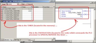
the reality of the situation is that the TON "timer" that you see in the Ladder Logic code is NOT REALLY a "timer" at all ... instead that object in the code is a TON timer "INSTRUCTION" ... the TIMER itself is actually located back (behind the scenes) in the processor's memory ... I've shown both the TIMER (in the memory) - and the TON INSTRUCTION (in the code) - in the figure below ...

note that in common practice, we ALL refer to the TON instruction (in the code) as a "TIMER" ... in normal context/conversation that's quite OK ... but ... technically speaking, the TON is actually an INSTRUCTION ... the word "instruction" being used here refers to a "command" coming FROM someone (from you the programmer) – and going TO someone else (to the PLC processor) ...

so ... (and this is the source of your confusion) ...

the TIMER (located in the memory) will not "run" – or "advance" – or "keep time" – UNTIL and UNLESS the PLC processor "updates" or "services" the TIMER – and that updating/servicing will not happen unless the TON INSTRUCTION "tells/commands" the processor to perform that updating/servicing operation ...

therefore ...

while the lengthy FAL instruction is grinding away – it is using up the processor's scan time ... and during that period, the processor is unable to read/see/execute the TON INSTRUCTION – and therefore the processor is unable to service/update/advance the TIMER in the memory ...

the end result of this is that the value in the timer's accumulator will advance in "fits and starts" ... in terms of peanut butter – we'd have "chunky-style" values – instead of "smooth and creamy" values ...

going further, in certain "high speed" operations, this effect can have some very "bad" consequences ...
.

TON_INSTRUCTION.jpg
 
Last edited:
Good explanation...I knew before even scrolling down to see the ladder that the OP was going to have an EQU statement....a common mistake and misunderstanding of TON. Instead of a LIM though I would use a GEQ and one shot...with a LIM you're still open to missing if you don't guess right on the spread.

Also it was mentioned that the ACC updates more than once per scan. Not true. It updates once per scan and that's why it can miss...if the scan time is 10ms then the resolution of ACC incrementing is by 10ms...that's why finite values can be missed. The timer ACC may go from 0 to 10 to 20 to 30....if you're doing an equal of 15 it will never be true.
 
Last edited:
Rung 1 test for the timer to equal 1000. If your scan time is greater than 1 millisecond, the ACC will skip numbers. If the scan time was 1.5 milliseconds it could go from 999 to 1001, and your test would fail. If your scan time is 10 milliseconds, you could easily go from 995 to 1005. Your test will fail 9 times out of 10. I don't know your system, but you might try changing your test from EQU to GEQ.
 
Thanks everyone for your explanation.

I basically overlooked the fact that timer.ACC doesn't really update unless the instruction runs every scan. Hence the whole

in terms of peanut butter – we'd have "chunky-style" values – instead of "smooth and creamy" values ...

and

if the scan time is 10ms then the resolution of ACC incrementing is by 10ms

really put things into perspective.

Ron your explanation never ceases to amaze me! Thanks mate.
 
I basically overlooked the fact that timer.ACC doesn't really update unless the instruction runs every scan.

Not quite correct. It only has to be scanned once every 68 mins before the .ACC starts flipping out.


Your problem is that it's very hard to make sure the PLC scans that piece of code EXACTLY 1000ms after the initial trigger. If your scan time is 3, 6, 7 or 9ms (flat) the EQU will never ever get triggered. At 3.003ms it should get triggered. At 3.006ms it would not. At 3.012ms it might. Etc.
 
Jeebs not sure what you mean by,

It only has to be scanned once every 68 mins before the .ACC starts flipping out.

I think you misinterpreted my statement as I meant that the tag timer.ACC only updates its value only when TON instructs the processor to update the timer(as explained by RON), hence updating once per scan.

My understanding now aligns with my observation, but thanks for your explanation anyway (y)
 
When you press F1:


How a Timer Runs

A timer runs by subtracting the time of its last scan from the current time:
ACC = ACC + (current_time - last_time_scanned)
After it updates the ACC, the timer sets last_time_scanned = current_time. This gets the timer ready for the next scan.
Important: Be sure to scan the timer at least every 69 minutes while it runs. Otherwise, the ACC value won’t be correct.
The last_time_scanned value has a range of up to 69 minutes. The timer’s calculation rolls over if you don’t scan the timer within 69 minutes. The ACC value won’t be correct if this happens.


So it was 69 mins. Close enough. :D
 

Similar Topics

I have a very amateur confusion regarding the interpretation of power supply rating for compactlogix power supplies. Initial assumption Any...
Replies
8
Views
9,346
dear all, doubts: 1)i am using simens-300,400 plc for the system integration. i want to know that the program which we are downloading in plc...
Replies
1
Views
2,058
Hello, all, I am new here and pretty new to PLC'S. Closest thing I have to PLC experience is with avionics. At my new job I am a welding engineer...
Replies
4
Views
769
I am working on some documentation in preparation for updating firmware around our plant. On one particular PLC, the point IO has two different...
Replies
5
Views
666
When enabling a FOR instruction does the index set to the initial value before the first execution of the Called Routine? e.g. Initial Value = 6...
Replies
4
Views
1,456
Back
Top Bottom