Analog: Not should I, but can I?

sparkie

Lifetime Supporting Member
Join Date
Nov 2014
Location
KS
Posts
1,148
I'm not a fan of doing it this way, but for various reasons, I need to do it this way. That being said, I've never sized up a 4-20mA circuit to do this. Each device in the circuit has ~250 ohm impedance (except the pressure transducer, I couldn't find one).

It looks like the analog card will feed power out, through the other devices and back to a (-) 0VDC reference.

The card can do ~900ohm max at 24V

Currently, the loop is being done this way with a click. What other info would I need to determine if this can be done without blowing up equipment?

W03CKYk.png
 
The pressure transducer is regulating the 4-20ma loop and is the AO (Analog Output) of the circuit. Too many devices in series will cause low inaccurate Milliamp readings, which do not harm the analog inputs. Power flows through the pressure transducer from the 24v supply, the pressure transducer is regulating a 4-20ma current based on pressure. The 4-20ma must travel through Device 1, device 2 and the PLC input, the PLC input is the analog signal return(not supply). The pressure transducer will modulate its internal current regulating circuit until it can produce the correct milliamp reading, (like someone constantly turning a potentiometer to the right milliamp reading).

Consider the voltage drop for longer cable runs.

If the pressure transducer is a Rosemont, I would say it could be fine looping several devices. If the pressure transducer is cheap, it may only be able to supply one device.

Most analog inputs are tough and some choose to use a 30-100ma fast acting fuse or optoisolators in the loop.
 
Last edited:
The pressure transducer is regulating the 4-20ma loop and is the AO (Analog Output) of the circuit. Too many devices in series will cause low inaccurate Milliamp readings, which do not harm the analog inputs. Power flows through the pressure transducer from the 24v supply, the pressure transducer is regulating a 4-20ma current based on pressure. The 4-20ma must travel through Device 1, device 2 and the PLC input, the PLC input is the analog signal return(not supply). The pressure transducer will modulate its internal current regulating circuit until it can produce the correct milliamp reading, (like someone constantly turning a potentiometer to the right milliamp reading).

Consider the voltage drop for longer cable runs.

If the pressure transducer is a Rosemont, I would say it could be fine looping several devices. If the pressure transducer is cheap, it may only be able to supply one device.

Most analog inputs are tough and some choose to use a 30-100ma fast acting fuse or optoisolators in the loop.

I'm not sure that you are correct for this analog card. I do believe that this schematic is the correct wiring according to the card manual. That 24VDC+ is tied to those analog inputs within the card, and they share a common reference, *I think*. Right now, the loop is working fine. My concern is that when I use a different analog card, it may change the behavior.
 
The 24 volts going to the card is providing power to the cards analog circuits. The cards communications are probably powered off of the backplane from the PLC. This allows you to use a different power supply for your analog inputs in case your power supply for digital IO is too noisy.

Page 39 shows the I+ as analog return.
https://cdn.automationdirect.com/static/manuals/p1userm/ch3.pdf
 
The 4-20 loop setup is common, you would be able to remove that card and use a Rockwell or Siemens.

If you choose an AI card that is non-isolated, the circuit will not work.
 
Last edited:
1. Loop resistance
If drive #1, drive #2 and the analog input are all 250 ohm inputs, the loop is not likely to work because that's a total of 750 ohms, which is a high loop resistance for loop regulated transmitter.

To confirm whether it will work or not, yes or no, you need the spec on the pressure transmitter, either

- its load line graph that shows how much total resistance in the loop the transmitter can drive.


H-W-ST3000-supply-voltage-vs-loop-resistance.jpg


- the statement that it requires a minimum lift off voltage (the lift-off voltage, plus drive #1 5V drop plus drive #2 5V drop, plus the AI's 5 volts drop has to be less than the power supply voltage. Since the Drives and AI drop 15 volts, that leaves 9 volts available to drive or 'lift-off' the transmitter; not enough.

The lift-off voltage in the load line graph is 10.8 volts, too much for a 24Vdc power supply. But if you can tweak the DC power supply to 26 or 27 volts (5+5+5+10.8 = 25.8V minimum) then it would work.

- the statement of how much loop resistance the transmitter can drive at 24Vdc

2. The pressure transmitter is 'floating' but if the drive inputs are not isolated and floating you could have ground loop problems.
 
2. The pressure transmitter is 'floating' but if the drive inputs are not isolated and floating you could have ground loop problems.

This has gotten me once. After a lightning strike destroyed two pump VFDs, A "new and improved" pair of VFDs were installed with the same (tested good) pressure sensor wired in series to both drive inputs. The new and improved drives had their analog inputs tied to the chassis ground in both drives and there was nothing I could do about it. Luckily we had a PLC nearby with spare analog inputs and outputs so my workaround was to use it as a signal isolator.

I keep a couple of 4-20mA signal isolators handy just for cases like this now.

These little bad boys are surprisingly compact, cheap, accurate and reliable, but sorta hard to order.
 
Last edited:
Alright, I'll get more specific here.

Pressure transducer:
Prosense SPT25-20-0100A
Manual: https://cdn.automationdirect.com/static/specs/prosensespt25transmitters.pdf

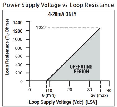
The curve there shows ~25-26V for 800 ohms.

Here is my loop power supply manual:
https://media.digikey.com/pdf/Data Sheets/Omron PDFs/S82K.pdf

It is the 15W model. The adjustment range is -10% to +15%. That gives me an upper range of ~27V.

That means:

(26V - 9) / 0.022 = 777 Ohms

Giving myself a little wiggle room that seems to be within range. I also did the power calc at 26V, which is just under 1W of power.

Am I missing anything here?
 
The curve there shows ~25-26V for 800 ohms.

That means:

(26V - 9) / 0.022 = 777 Ohms

Giving myself a little wiggle room that seems to be within range. I also did the power calc at 26V, which is just under 1W of power.

Am I missing anything here?
No. Your arithmetic is good.
I would crank the power supply up to 26.5V for a tad more wiggle room but your calc is correct. And I'd put a label on the power supply stating the 26V output is required to run the pressure loop, otherwise, down the road someone will replace the power supply with a standard 24V output and the loop will stall at some loop current around 19+ mA.

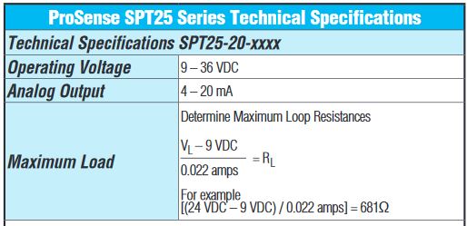
For those who read this later and wonder why those numbers are used, the maximum load calculation is an Ohms Law calculation E/I=R:

(power supply voltage minus lift off voltage (9V)) / 0.022A = maximum load resistance in Ohms


A-D-SPT25-PT-specs-and-max-load-calc.jpg


Lift Off voltage is the minimum voltage needed to run the transmitter with no load, the voltage shown on the load line where the load crosses 0 Ohms resistance:


A-D-SPT25-PT-loadline-9-Vdc-lift-off.jpg
 
I would really caution against making a permanent installation that requires more than 24VDC. Main reason being if a power supply fails, and someone replaces it, will they know to adjust it to 26.5V? Or will they leave it at 24V, and suffer strange, intermittent issues that are extremely difficult to troubleshoot? Or will they measure 26.5V while troubleshooting another problem, and assume it must be corrected and set to 24V, thereby causing this new issue they weren't expecting?

Just something to consider.
 
I'm not really making it, I'm just not changing what is there. I understand the concern, though. Hence the title.
 
No. Your arithmetic is good.
I would crank the power supply up to 26.5V for a tad more wiggle room but your calc is correct. And I'd put a label on the power supply stating the 26V output is required to run the pressure loop, otherwise, down the road someone will replace the power supply with a standard 24V output and the loop will stall at some loop current around 19+ mA.

For those who read this later and wonder why those numbers are used, the maximum load calculation is an Ohms Law calculation

Thanks for the info. And good idea about labeling supply.
 
If your circuit is correct and the analog outputs are spare why not connect them to the VFD's and map the input to the outputs.
 
If your circuit is correct and the analog outputs are spare why not connect them to the VFD's and map the input to the outputs.

Those are actually for future use on this FleetZoom module. I'm not putting them in as that is my fallback to get it up if I run into trouble. The concession was made to not touch the drives or the PID loop in order to keep cost down for this particular job.
 

Similar Topics

hello.. i wanna add the value of an analog input value to the PLC existing system in my plant, i use OMRON CS1G-CPU45 and the analog input module...
Replies
0
Views
3,679
Good afternoon, I am currently working with an HMI/PLC LP-a070 and I require at least one analog output, but the PLC does not have one. I was...
Replies
5
Views
105
Hi all. Customer wants analog faceplates really bad, even if we explained that it doesn't make much sense in his process. What he wants to see...
Replies
5
Views
110
I'm having trouble calming down 2 Tempo Sonics. I'm using Studio 5000 CompactLogix my Raw value is jumping around from 8575.0 to 8755.0 at a...
Replies
30
Views
1,127
I cannot add SLC500 analog input tag (I: 8.3) to EZSeries Touch Panel Editor (V 5.3). I used all the listed tag datatype but it all says "Invalid...
Replies
10
Views
257
Back
Top Bottom