The symbol shown in the ladder diagram can be thought of as a contact that is...

Of course, a pushbutton is not a relay though, is it?

A pushbutton is (can be) part of wiring the relay-logic.

But even then:

if I want to know if

- the coil of a NO-relay contact is 'energised' I will use ---| |---

- the coil of a NO-relay contact is 'not energised' I will use ---|/|---
- the same goes for NO- and NC-pushbuttons.


So both ---| |--- and ---| / |-- can be used for a NO or NC-relay contact and a NO or NC-pushbutton-contact.

Thus using the term NO-contact for --| |-- and --|/|-- for an NC-contact can not be correct. This because every contact has 2 state's: on or off

--| |-- = ON = 1 = TRUE = 24Vdc

--|/|-- = OFF = 0 = FALSE = 0 Vdc
 
PLC "Ladder" software emulates relay operation and logic by having the hardware input act as a relay coil. Then in software, just as in wiring physical relays, you select the N.O. or N.C. contacts to build the logic and the desired operation.
 
The thing that throws people is if you use a normally closed input device of any kind as a plc input you would not then use the "normally closed" contact type for that input in the plc to perform the equivalent function.

As ivo.maenen shows, a normally closed stop pushbutton input used for a run latch would show up as a "normally open" contact in the plc program. This relationship is true whether the input device is a pushbutton, a relay or a sensor.

Only those coming to plc programming for the first time who who have also had some experience with physical relay logic systems would have an appreciation for this. "Back in the day" it was very common to expand a physical device's state information by using it to drive the coil of a multi-pole relay (or two or three). So those of us who have worked on these systems have seen this "drawing style" before. For those who haven't seen this before it isn't as intuitive. Back when all we had were physical relays we had no choice. State expansion by relays is just what you had to do. That is not true anymore.

Ladder logic was the conduit that allowed new plc users in the '70s and '80s to immediately jump into plc program design because of previous design familiarity. Because that base design experience is no longer there for new users, some of the constructs and terminology used in ladder logic can be an impediment to new users. I'm not saying we should scrap ladder logic. I think it is the best available graphical design and display method for Boolean logic. But we do need to acknowledge that some of the naming conventions that were used in the early days of ladder logic might not be the best for today's users.

Keith
 
Originally posted by jaden:

In the PLC programming classes that I teach, I can easily identify students that are familiar with using real relays. The logic development is just more natural to them.

That makes sense. What are you seeing for percentages of students who appear to have have real world relay experience (judging by how quickly they grasp ladder logic) versus those who don't and what are their age distribution?

Keith
 
Last edited:
In the PLC programming classes that I teach, I can easily identify students that are familiar with using real relays. The logic development is just more natural to them.

A subject that I don’t believe has been discussed in this thread is the PLC descriptor/tag format. It is generally accepted that the description should be what the I/O point is when it is a “1” (on, NO is true, etc. etc.).

Just describing something as “Lift solenoid” is worthless. Does energizing that output mean the lift will raise or will it lower the lift.

Same thing with input descriptors. “Hydraulic pressure switch” tells me nothing. If it is a “1” is the pressure high, low, or what?
 
Last edited:
Originally posted by dogleg43:

It is generally accepted that the description should be what the I/O point is when it is a “1” (on, NO is true, etc. etc.).

And that gets us right back to our normally closed stop pushbutton. The tagname or description shouldn't be "Line_Stop_PB", it should be "Line_Not_Stop_PB".

Keith
 
PLC "Ladder" software emulates relay operation and logic by having the hardware input act as a relay coil. Then in software, just as in wiring physical relays, you select the N.O. or N.C. contacts to build the logic and the desired operation.

This is the first time I've read (or heard) this explenation.

So every input (NO or NC...whatever kind of hardware) is wired to an internal auxillary relay and the NC- or NO-contact of this auxillary relay is evaluated inside the program with --|/|-- or --| |-- and then controlling the power relay ---( )--

o_O

A strange kind of old school relay logic....

I think of old school relay circuits like this:

https://qph.fs.quoracdn.net/main-qimg-5fe292f71513861e1d56196f4903bd9c
 
A subject that I don’t believe has been discussed in this thread is the PLC descriptor/tag format. It is generally accepted that the description should be what the I/O point is when it is a “1” (on, NO is true, etc. etc.).

Just describing something as “Lift solenoid” is worthless. Does energizing that output mean the lift will raise or will it lower the lift.

Same thing with input descriptors. “Hydraulic pressure switch” tells me nothing. If it is a “1” is the pressure high, low, or what?

I don't necessarily agree with this statement. If I happen to have NO, NC, metering/metered devices, etc, I will put it in the description, but I don't want all that extra information clouding up the prints when I'm trying to read them.

For instance, I read it in my head similar to:

If the System Bypass bit is Not Set, the Stop Button is Not Pressed, the start button IS pressed and the Run Permissive Is set, latch in the Motor Starter Output.

I'm perfectly fine with looking at a wiring diagram or a device to see if it is NO or NC. In fact, it isn't very often I find myself wondering which it is. I put the extra info in rung comments rather than instruction comments or a point's tag name.
 
Gracious ...

if I were a beginner trying to understand PLC stuff – I'd be thoroughly and helplessly confused by reading this thread ...

folks – it ain't that complicated ...

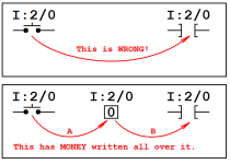
what's happening is that most contributors are trying to draw a relationship directly between the FIELD DEVICE (the button) and the INSTRUCTION (the XIC) used in the Ladder Logic code ... as shown in the top figure below – that is NOT the way it works ...

SECRET HANDSHAKE: in the top figure we're mistakenly leaving the BIT/BOX (which exists in the PLC's memory) – completely out of the discussion ...

the bottom figure shows that the status of the FIELD DEVICE (the button) directly affects the ONE or ZERO contents of the BIT/BOX ... in GENERAL/BASIC terms, if there is "electrical current" flowing through the button – then the BIT/BOX will contain a status of ONE ... if there is NO current flowing - then the BIT/BOX will contain a status of ZERO ...

the "updating" of the BIT/BOX – as to HOW it happens – and just as importantly, WHEN it happens - is another lesson – for another time ... and the lesson can be fundamentally different when discussing different PLC platforms ... (example: WHEN the updating happens is different for an SLC platform – than for a CONTROL-Logix platform – and different again for a COMPACT-Logix platform – and so on ) ...

for this discussion – let's just say that the BIT/BOX gets updated as shown by Arrow A – and move on ...

at some point in the "scan sequence" – let's say that the processor executes the XIC INSTRUCTION in the Ladder Logic code ... now it really makes NO difference what you call this doodad ... "Examine If Closed" ... "Normally Open" ... or even "Sam's Little Brown Dog" ... specifically, it makes NO difference what you choose to call it – as long as you know exactly what the INSTRUCTION tells the PLC processor to do ...

and it ALWAYS – ALWAYS – ALWAYS just tells the processor to "Go Look For A ONE" in the BIT/BOX with the specified address ...

if the processor finds a ONE – then it's happy – and the instruction will be evaluated as TRUE ... if the processor does NOT find a ONE – then it's unhappy – and the instruction will be evaluated as FALSE ...

this execution/evaluation of the Ladder Logic code is shown as Arrow B – in the bottom figure below ...

and once again, HOW it happens – and just as importantly, WHEN it happens - is yet another lesson – for yet another time ...

all of this is explained in the eleven YouTube videos that I linked earlier ... and I can PROVE that it works this way by demonstrating the simple experiments shown in those videos ...

now to be truthful ... over the years I have had MANY people ask this question:

"But, Ron, if the way that MOST people are WRONG in the way that they believe (and teach) even the most basic concepts behind how a PLC works – then how do they get away with that?" ...

there's a simple answer to that perfectly valid question ... here's an analogy ...

several thousands of years ago, everyone KNEW that the earth was FLAT ... and here's the secret handshake ... it's perfectly OK to believe that the earth is FLAT – just as long as you don't go too far in any one direction ...

even today – if you (or I) are planning to drive from coast to coast – we reach into the glove compartment and we pull out a FLAT road map ... specifically, we do NOT pull out a round globe ... now the round globe would be a more accurate representation of the trip that we're going to make – but a FLAT map is perfectly OK – as long as we don't go too far in one direction ...

but ...

suppose that we travel in a straight line for about 25,000 miles in any one direction ... now suddenly we're faced with a monumental problem – because now we're right back where we started from ...

here's the point ...

as long as you're trying to understand PLC Ladder Logic – and you stay at the BEGINNER LEVEL – then you can literally get away with murder ... there are any number of ways of explaining things to a beginner that can sort-of-kind-of make sense – and allow him to sort-of-kind-of handle BEGINNER LEVEL problems and programming questions ...

the big issue comes into play when the student eventually leaves the "safe space" of the classroom - and starts working on BEYOND BEGINNER LEVEL problems in the field ...

so ...

you can completely ignore the presence – and the function - of the little BIT/BOX while you're reading – (or in many cases even WRITING) – a piece of Ladder Logic code ... as long as the sun is shining – and the birds are singing – and the pope gets his Wheaties on time – then life is lovely and a flat road map is "close enough" ...

but ...

when you're called upon to TROUBLESHOOT a PLC-controlled system which is NOT working correctly – then sometimes (I'd say "often" times) you're going to need a BEYOND BEGINNER LEVEL understanding of what's REALLY going on under the hood of this thing ...

party on ...
.
SCAN.PNG
 
Last edited:
even today – if you (or I) are planning to drive from coast to coast – we reach into the glove compartment and we pull out a FLAT road map

Hi Ron,

I dont think they make maps anymore, everything is done on the phone :)

(PS how's retirement ?)
 
I dont think they make maps anymore, everything is done on the phone

no, thankfully you can still find paper maps here and there if you look for them ... that's good for me – because I'm still using a basic old flip-phone ... one of these days those new-fangled gadgets are all going to go belly-up – and then all of you modern folks are suddenly going to be lost ...

PS how's retirement ?

I'm still resting up from moving all of my gear out of the office space ... soon I'll have to start sorting things out and straightening up the garage and my workshop ...

in the meantime – I've been doing quite a bit of warfare against the evil forces of encroaching vegetation ... (mowing the lawn, trimming bushes, etc.)

here’s a thought about the nice folks who "congratulate" me on my retirement ... I know that they mean well – but consider this:

suppose that a guy sincerely LOVES his job – and that he gets paid handsomely to do it ...

when you congratulate him on being retired, you're actually saying:

"Sorry you don't get to do the job that you used to love anymore – oh, and by-the-way - whatever else you do instead from now on – you won't get paid to do it."

anyway ... I'm still getting calls from customers wanting to set up classes – but that ship has officially sailed (my lovely little wife says so) ... still – I never say "never" ...
 
Last edited:
I often add more information to the description.
Such as:
Screw Speed Switch
1=Ok to run

Love it!!
Using “Not” in a descriptor throws me off because if a NC contact is used then in my mind I’m thinking “Not plus a Not”. Makes me think of Jethro Bodine (you may need to be over 50 to understand).
 
As most people that read this forum understand, when Ron writes comments people pay attention.

I have taught PLC classes for well over 12 years and for the last 6 or so years I do things very differently than the first 6 years.

After reading Ron's forum comments over the years I realized we were doing it completely wrong. I threw away the darn PowerPoint slides and long lectures. I now use the problem solution method that Ron has championed and it works really well in teaching maintenance folks.

Nobody falls asleep and breaks are on an needed basis. As in I really need to take a leak....

I also realized that separating the instruction from the address and teaching these as two different things was the key to getting people to see the light. The bit box analogy works very well.

I for one would like to thank Ron for helping me to "see the light" and become a much better teacher/instructor/mentor to the next generation of maintenance folks.

I am also sad to see you get out of what you love to do. I have worked with PLCs and automation for well over 30 years and have always loved it. In the future, when I get out of this business, I will also greatly miss it.
 

Similar Topics

Sorry for the missing JPG If the Electrical symbols shown are used for Pushbuttons which symbol will you use for a “Two Hand Tie Down Optical...
Replies
15
Views
8,988
Hello everyone, Recently, my Archestra IDE shut down while I was editing. After restarting the IDE, I noticed warning symbols under my opened...
Replies
1
Views
95
I was looking for this function, so that i doesn´t need to do it in the PLC. If there are an alarm in the alarm list, i want to flash the...
Replies
2
Views
492
Hello, fairly new to plcs I’m tasked with installing a PE to a micrologix1200, in the attached picture I/14 is the PE I’m installing it’s going to...
Replies
6
Views
938
Hello Thank you all for your support. I am actually experience same issues with TIA portal V17 update5 as well as V18. The problem is with the...
Replies
0
Views
794
Back
Top Bottom