Siemens 331-1KF02-0AB0 4-20mA issues

dan_cup

Member
Join Date
Jan 2021
Location
Uk
Posts
9
Hi all,

i have a problem with the above card, my rack has two of them and the same issues!

In Channel 0 and 1 on both cards i have 2 wire sensors which read correctly, the - from sensor is connected to I+ and M- is to ground.

Channel 2/3 are deactivated.

Channel 4/5/6/7 are 4 wire sensors. When i connect these the PIW reading from the other channels go funny.

I have confirmed each individual channel by inputting 4-20ma and its perfect.
I have also checked the sensor mA with a multimeter in line and confirm they all read a value true to the sensor position.

To rule out 2 wire and 4 wire messing the card i have moved all the 4 wire onto 1 card and deactivated all channels except 0. when i connect 4-20ma simulator i get 0 - 27648 but when i connect the first sensor i get 864 even though its sending 19.56mA to the card. please see picture

Im confused by this behavior.
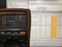
4 wire.jpg
 
When the values from existing analog inputs on multiple input cards suddenly go crazy when another channel is added is the classic sign of a ground loop/common mode issue.

The ground at the field device's analog output is at a different potential than the ground at the PLC's analog input card. That difference in potential is "commmon mode voltage".

A difference in ground potential creates a current between the two points because that's physics.

The ground loop current adds or subtracts to the 4-20mA current-loop current and
- if the resulting current it's within range of the A/D, you get a different value,
- if it's out-of-range, it saturates and goes off scale, upscale or downscale depending on the polarity of the ground loop, and
- if the common mode voltage exceeds the limitation of the AI card, it smokes the Analog input, usually the entire card.

In 15+ years of forum participation, I know of only one instance of an HVAC guy tracing a ground loop in a lighting system and fixing it. Siemens' instance on an "equipotential" site is a reference to the fact that the site is supposed to have the same ground potential everywhere. Yeah, sure, not in the real world, only in the dreams of a Teutonic engineer.

For the rest of us, a ground loop is fixed by using a 4-20mA repeater/isolator module that isolates the input 4-20mA from the field device, from its output going to the analog input. One for each input.

2-wire, loop-powered 4-20mA circuits are typically isolated from ground, so if the same power supply is used for loop power, 2-wire 4-20mA signals rarely are the source of ground loop problems. 4-wire devices are the culprits.
 
Last edited:
Thank you some interesting points.

I should add for context that this machine was running with s7-400 plc but we are now fitting a 300 plc so the AI cards are wired a bit differently.
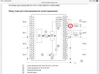
That said I’ve wired them as per how they are used on other types of machine we have. This includes systems just like the examples found in the manual. The only thing I could see I had missed since writing the original post from the manual vs how our machines are is the red circle.

I added a link to all the M- on the card and tried with just this channel enabled and it worked! 19.56mA showing 26400ish. I then enabled all the other channels and they all went to mid range 13500 area.

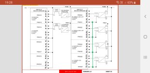
I then decided that as the 2 wire ones were displaying ok with the 4 wire sensors out that I would only link the M- on the 4 wire sensors.

I now have values I would expect in all channels!

I’ve attached how my card is wired- green being the addition.

F74CAAEC-009C-411E-A43B-2BFCD8FBB807.jpg ED92B520-0F9F-4CB7-AFB2-729997C2D683.jpeg
 
I seem to remember that those cards have four black config modules inserted tin the side, these can be rotated to the required type i.e. active, passive, 0-10v, 4-20ma, are you sure these are in the correct positions.
 
I seem to remember that those cards have four black config modules inserted tin the side, these can be rotated to the required type i.e. active, passive, 0-10v, 4-20ma, are you sure these are in the correct positions.

Thanks parky, that is the 7KF02 card with 20 pins, this is the 1KF02 card with 40.

This card has nothing on the case to adjust
 
Siemens' instance on an "equipotential" site is a reference to the fact that the site is supposed to have the same ground potential everywhere. Yeah, sure, not in the real world, only in the dreams of a Teutonic engineer.
Equipotential bonding is a requirement of EN60204-1.
Since dan_cup is from the UK, EN60204-1 applies to him.
I am surprised that there is no such requirement in the US.
 
The ground at the field device's analog output is at a different potential than the ground at the PLC's analog input card. That difference in potential is "commmon mode voltage".

thinking about this, do you mean if I am taking the 24Vdc and the 0v from out on the site, from a junction box say it can be different potential?

In my machine the 24Vdc, Ov and 4-20mA +/- all come from the main panel and go to the sensor in a 7 core cable.
So the PLC and the sensor are using the same 24v/0v.

Surely this mean the potential is the same, or do you mean the external machine is not ground well enough?
 
Some sites have a buried ground rod 'network' that keeps the ground potential the same (equipotential, as Siemens likes to say).


Other sites do not and there can be different ground potentials at different locations.


Not all ground potentials are equal.


In your case, a 2-wire loop powered instrument is likely to be isolated. It will have an earth ground connection for safety, but the signal output is isolated from the earth ground. Ground loops are not a factor.


A 4-wire device might have an isolated signal output, but many do not. Analytical sensors frequently do not. The ground reference for the output circuit is eventually the local ground potential where the device is installed.


Depending on the magnitude of the potential difference and the level of isolation in the input circuitry, the difference in ground potentials shows up as an offset or damage, depending on the magnitude of the difference.
 

Similar Topics

Why when i connect all the 8ch of Analog Input(4-20mA) into the 6ES7 331-1KF02-0AB0 module the 4-20mA reading is not correct. example the input...
Replies
3
Views
2,933
I've been fighting a problem with this 8 channel analog input card mentioned in the title. I believe it's something I'm doing in the wiring but...
Replies
3
Views
1,717
Hello Experts, I need your help about this issue of mine about my Siemens Analog Input Card SM331 having SF LED lit. I know this is system fault...
Replies
2
Views
4,483
Hello All, Want to know what should be the correct setting for the Measuring range for connecting this instruments to my AI Card? So I am...
Replies
0
Views
2,398
Hello Experts, I am going to be integrating an AI module into an existing panel and wants to know what should be measuring range setting when i...
Replies
0
Views
1,883
Back
Top Bottom