Loading zeros into FIFO

tewildrick

Member
Join Date
May 2020
Location
Indiana
Posts
3
1st post here, but have been lurking for months. I have found the threads here extremely helpful. I've been struggling with this issue for the last day or so and am at a loss for what is going on.

PLC: 5069-L340ERS2
Programmed in: Logix 5000 v32.11

I'm using a FIFO to store downtime data for a production line. I am using a 4 DINT array to hold Line #, Fault #, Machine #, and Time in Seconds. I have a status tag that changes value depending on inputs from various photoeyes. If the value is not equal to 0 (meaning faulted) the "running time" information is placed in the array and a status change bit is triggered to load the FIFO. When the value goes back to 0 (running) the "downtime" gets loaded into the FIFO.

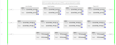
It seemed like a simple solution. Issue is that the downtime works but the runtime info is getting lost. I placed MOV's at the end of the routine to monitor the 4 DINTS, the FFL, and the 4 DINTS that the data is unloaded to and I can see the downtime values get loaded and unloaded but the uptime values aren't transferred from the array to the FIFO so its four zeros in and four zeros out.

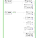
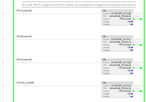
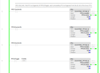
Attached pics of the logic for reference.
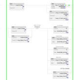
Fifo1.PNG Fifo2.PNG FifoCheck.PNG FifoLoad.PNG FifoUnload.PNG
 
EDIT: Welcome to the forum :)

The tag "Status_Change" is written as an OTE in both rung 9 and 11.
So, no matter what "Status_Change" is set to at rung 9, it will always be "reset" at rung 11 since you have a oneshot in front of it.

From your explanation i belive that rung 11 is the Downtime, which would explain why only that is working.

Try to use 2 different bits for runtime and downtime status change instad of the same.
 
That was it. I had thought of that yesterday, but obviously didn't try it.:whistle:

Next question is will I run into issues if I copy rungs 9 and 11 for other areas using the same status change bit(s) that I'm using now?

Basically there's 10-12 machines or "areas" that I'm looking at, will I need a different bit for each or can I use one "uptime" and one "downtime" status bit for all?

What you could do is to change the 2 OTE instructions to OTL, which will latch the "STATUS_CHANGED" bit and then make a new rung after the FIFO's where you use an OTU to unlatch the "STATUS_CHANGED" bit.

This way you will be able to copy your existing uptime and downtime code to the rest of the machines, and not have to create a new status change bit for each machine. Just make sure that the rungs with the FIFO's and the OTU are always scanned last.
 
another thing I noticed is that your FFLs and FFUs happen on different scans because of the ordering: status_change triggers [4,0]; [4,0].EN triggers [4,0] on the next scan; etc.


All four FFLs can be triggered on the same scan when status_change has a rising edge, because each separate control blocks keep track of the rising edge for its own FFL instruction.


Also, using one bit and OTLs+XICs to trigger FFLs and OTUs+XIOs to trigger FFUs should work, as suggested by Jobbe, but it will trigger one or the other on the first pass.
 
I wouldn't of used a FIFO for this.

An array of a UDT with your required fields will be much easier to administer.

You wont need to load and unload, just increment a pointer after every fault is recorded.
 
another thing I noticed is that your FFLs and FFUs happen on different scans because of the ordering: status_change triggers [4,0]; [4,0].EN triggers [4,0] on the next scan; etc.


All four FFLs can be triggered on the same scan when status_change has a rising edge, because each separate control blocks keep track of the rising edge for its own FFL instruction.


Also, using one bit and OTLs+XICs to trigger FFLs and OTUs+XIOs to trigger FFUs should work, as suggested by Jobbe, but it will trigger one or the other on the first pass.


Thanks, I wasn't sure if that'd work or not. I've ran into instances where it seems like using the same bit on multiple lines causes some of them to not evaluate.

I wouldn't of used a FIFO for this.

An array of a UDT with your required fields will be much easier to administer.

You wont need to load and unload, just increment a pointer after every fault is recorded.

The reason for the FIFO is two-fold. First is the FIFOUToggle (unload) bit is being controlled by an Ignition script to write the data to a SQL database. Idea being if we lose communications to the gateway we can still store 100 entries before losing data. When operating normally the data is written and read right away.

The other reason for the FIFO is, I think, my boss is old school and that's what he knows. :D
 
Easiest way to do shift registers is with the copy instruction on an array, upside down.
Do not nee the FIFO instructions at all.

Copy the Array Element from position #1 to position #0, for a length one element short of the array length.
Fresh data goes in at the bottom of the array, and is shifted Up one element for each execution of the One-**** COP instruction.

Array[0-100]
COP Array[1], Array[0], Length 99.

So much easier, as long as you remember the shift is upside-down.
Descriptors on the source and destination help.

I concur with this advice. There are a couple of cases where I have used the FFU/FFL pair. In cases where you need to make use of the built in overhead created for you with the control address, those instructions can be useful.
That is usually cases where the quantity of data in the "stack" is variable which is sounds like is the case here.

The key thing I learned early on is that you need to unload before you load if the stack is full. If I use the FFU/FFL pair, I will program them in that order and with the right conditions so that I am not loading first, then unloading which can result in a stack with an extra duplicated value or one too few in the position register.
 

Similar Topics

How can I access the web page that allows me to see and upload the pcl or translation file into my Pl1000E? My Pl1000E doesn’t have an ethernet...
Replies
2
Views
120
Hi guys, I have had some issues with uploading a program from a Micro 850 PLC. This is the first time connecting so I don’t have a file on my...
Replies
8
Views
261
Hi everyone, I want to upload the program from my CPU317TF-2 DP to my PC via connecting to CP 343-1 Advanced since it has LAN ports and the CPU...
Replies
1
Views
155
Hi all, Im stuck trying to support a client with Motorola ACE.. I was able to upload all of the other sites to STS but one. Im working remotely...
Replies
0
Views
106
how do you load from [A] floppy disk to laptop 9030 program
Replies
3
Views
146
Back
Top Bottom