Help with flow curve controllogix

asterof

Member
Join Date
May 2007
Location
Califonia
Posts
554
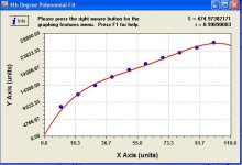
I need some controllogic code to create this flow curve
Been trying to figure out a way to do this is a clean and
accurate manner.
The analog input module is configured for 4-20 ma = 0-100 inches of H20
The physical calibrated flow measurements come out to this
0 0 LBM/H
10 8222 LBM/H
20 11628 LBM/H
30 14241 LBM/H
40 16444 LBM/H
50 18385 LBM/H
60 20140 LBM/H
70 21753 LBM/H
80 23255 LBM/H
90 24666 LBM/H
100 26000 LBM/H
as you can see even tho the 0-100 inches of h20 across
the orifice place is linear, the actual volume of material
is not. So I need a code snipit that can produce this curve.
Willing to compensate for the time, I need it by Monday Morning
Thanks
 
Couldn't you plot that in excel and determine an equation for the line using a trend line and then use the CPT instruction once you have the equation?
 
The Honeywell PAC I use has a function block called FGEN, stands for function generator.

I'd never used it, but I recalled it from seeing your table of values. So I searched the H-W manual for look-up table (no hits), linearizer (no hits), characteri (hit) and this is what turned up:
2wlre6h.jpg


I gotta believe that A-B's CLX has something equivalent.

If you do a .pdf search, remember that characterize/characterise and linearise/linearize get spelled two different ways.

Dan
 
The trick is fitting an equation to the data points using least squares

asterof, the problem is knowing the form of the equation you want to fit the data to. If it is y=c0+c1*x+c2*x^2 then it is easy to find the coefficients c0,c1 and c2 that minimize the squared error.
I will give someone else a chance to be the hero.
 
I'm sure there are a few ways

but I messed around with it to long, now I don't really have the time to trial and error it, so i was looking for someone
to toss me a snippet that would work and I would compensate them for their time.
Thanks
 
I have the answer.

I am still giving someone else a chance to be the hero.
BTW, the data fits very well.

Couldn't you plot that in excel and determine an equation for the line using a trend line and then use the CPT instruction once you have the equation?
What equation? Is the equation a polynomial? Does it have trig functions? sqrt, gamma, log or exponential functions? What equation are you going to fit to the data? Once you know that the answer is easy.

That function generator may work. I bet if it does a cubic interpolation between the points it would be very close.
 
I must be missing something obvious if Peter is asking about it but I am not sure what it is.
 
Actually what i did was create a UDT of arrays
containing the X1,Y1, X2 and Y2 variables
Then as you all suggested I used the FGEN
and pointed the arrays to the FGEN, it seems I needed to also
assign empty array values to the X2 and Y2 in order to get it to compile. Seems to work doing it this way.
Thanks I tried that once before but did not know you had to also
assign an empty array to the X2 and Y2. Odd way of doing it
 
Interesting file, but leave it to me

I got the Fgen working in a FB logic file
Then I decided it would be cool to turn it into
a AOI instruction

So I created an AOI using an FBD
with an input, output, X1, Y1, X2, Y2 Array
I called it Flow_Curve

The idea was to drop the instruction type Flow_Curve
into the standard logic file and enter the
input tag, output tag, X1 array (in this case the array
that contained the ten variables 0,10,20 and so on) and the
Y1 Array in this case the array that contained the 0, 8222
and so on). OOPS problem
In the parameter section of the AOI it does not seem to allow
passing an array
I will download the working logic
in next message
 
here is acd

here is the file, just rename the .txt to .ACD
and if you an figure out how to use local parameter
arrays in an AOI let me know
thanks
 

Similar Topics

Hello guys, I need some help. I read all the old posts on hall effect sensors but none dealt with my module. The system uses a Gemco 194761 RFO...
Replies
3
Views
1,708
Hey guys, I have MLX LOGIX1400 running fine except that it faults sometimes on math over flow. I examined the program and spotted a...
Replies
8
Views
2,314
So I have an ABB TotalFlow uFlo G4 unit and have configured it's COMM port as Modbus Slave. I have also mapped internal 32Bit Float Registers to...
Replies
9
Views
5,804
Hello all, I've got to make a totalizer for our digester acid fill using rslogix 5. I have a flow transmitter scaled for 0-16000 LPM using a CPT...
Replies
9
Views
5,100
I have a ABB Totalflow 6213. is anyone here knows how to change the display to show from PSIA to PSIG ?
Replies
0
Views
1,321
Back
Top Bottom