Allen-Bradley “Latches” vs. Direct Logic “Sets” ... round 1 ...

Ron Beaufort

Lifetime Supporting Member
Join Date
Jul 2002
Location
Charleston, SC
Posts
5,701
Greetings to all,

for those who aren’t totally tired of the “latch or don’t latch” discussion in this recent thread, here is one more little item that may interest those of you who work with Direct Logic PLCs from Automation Direct ... the next several posts discuss the very basic ideas behind the “retentive memory ranges” for those systems ...

first of all ... a preview of where we’re going with this ... we’ve already discussed (in that earlier post) that with an Allen-Bradley system, if we want a particular output to “come-back-up-in-the-ON-condition” after a processor power cycle, then we would normally use a “latch-on” arrangement rather than a “seal-in” construction ... so the question now becomes: “suppose that I’m using a Direct Logic system and I need the same functionality?” ... well, Direct Logic processors don’t have “latches” and “unlatches” like the Allen-Bradley processors ... so ... with a Direct Logic system, the simple answer is to use the “SET” instruction to turn the output ON ... and to use a “RESET” instruction to turn the output OFF ... so is that all there is to it? ... stay tuned ... you might be unpleasantly surprised ...

WARNING! ... the following material may not be suitable for young programmers ... parental discretion is advised! ...

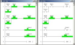
next - just so that we can compare apples to apples – here is a simple “before and after” screen shot of an Allen-Bradley program ... the basic idea is that we have two simple “seal-in” type rungs and two simple “latch-on” type rungs ... in the “before” condition on the left, the control bits for all four “Pumps” have been turned ON by their respective rungs ... as we’ve discussed in tedious detail throughout the previous thread, with an Allen-Bradley system, the “latched-on” rungs are “retentive” ... the “sealed-in” rungs are NOT “retentive” ... specifically, after a processor power cycle, the “latched-on” rungs WILL come back up in the “run” condition ... the “sealed-in” rungs will NOT come back up in the “run” condition ...

[attachment]

and ... as shown in the “after” screen shot on the right ... there are no real surprises here ... sure enough, after a processor power cycle, the “latched-on” rungs DID come back up in the “run” condition ... the “sealed-in” rungs did NOT come back up in the “run” condition ...

so now the stage is set ... on to the Direct Logic system in the next post ...
ab before and after.jpg
 
Allen-Bradley “Latches” vs. Direct Logic “Sets” ... round 2 ...

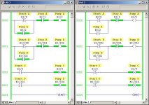
here is a simple “before and after” screen shot of a Direct Logic program for a DL230 processor ... the basic idea is that once again we have two simple “seal-in” type rungs ... and again we have two simple “latch-on” type rungs ... of course, this time we have to call these “set-on” type rungs to match the Direct Logic instructions ... in the “before” condition on the left, the control bits for all four “Pumps” have been turned ON by their respective rungs ...

[attachment]

so now ... let’s see if anything different happens when we run this Direct Logic program through the same power cycle test that we ran with the Allen-Bradley system ...

and ... as shown in the “after” screen shot on the right ... there are some ! MAJOR ! differences with this system ... specifically, after a processor power cycle:

in rung #4 ... Pump D which was “set-on” DID come back ON ... we expected that to happen ... BUT ...

in rung #3 ... Pump C which was also “set-on” did NOT come back ON ... that might be a surprise to some of you ...

going further ...

in rung #1 ... Pump A which was “sealed-in” did NOT come back ON ... we expected that to happen ... BUT ...

in rung #2 ... Pump B which was also “sealed-in” DID come back ON ... and that might be another surprise ...

golden nugget of truth:

good programmers don’t like “surprises” ... even in the best of situations, surprises cost time and money ... in worse situations they can cause injuries and death ... if you’ve been even slightly surprised by what you’ve seen so far, then I strongly suggest that you stay tuned for the rest of the story ...

quick recap ... at this point we’ve seen that a Direct Logic program written with almost EXACTLY the same structure as an Allen-Bradley program can have MAJOR differences in its operation after a processor power cycle ...

MOREOVER ...

we’ve seen that certain Direct Logic rungs having EXACTLY and PRECISELY the same structure as OTHER Direct Logic rungs can have MAJOR differences in their operation after a processor power cycle ... so ... are we having fun yet? ...

ok ... here’s the secret handshake ...

the ADDRESSES used in rungs #1 and #3 are NOT located in the “retentive range” ... BUT ... the ADDRESSES used in rungs #2 and #4 ARE located in the “retentive range” ...

this “retentive range” that we’re going to talk about next is something that Direct Logic processors HAVE ... but which Allen-Bradley processors (for better or for worse) do NOT have ... and I’ll guarantee you that there are a LOT of Direct Logic programmers out there who are not even aware that these “retentive ranges” exist ... and more importantly ... they don’t know about the ! SERIOUS ! SAFETY ! ISSUES ! that this concept can present ...

and now ... on to the next post ...

dl before and after.jpg
 
Allen-Bradley “Latches” vs. Direct Logic “Sets” ... round 3 ...

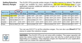
here is a screen shot from page 3-16 of the User Manual for our Direct Logic DL230 processor ... you can find this chapter of the manual here if you want to do more research ...

[attachment]

first of all ... notice how little (well, actually NOTHING) is said here about what the “retentive ranges” mean to the ! SAFETY ! aspects of the system ... this is one reason why I can assure you that many (most?) Direct Logic programmers have never even considered the issues that we’re discussing here ... specifically, the book doesn’t dig into it ...

next ... notice that besides the “C” (control relay) addresses which we’re presently discussing, there are also “retentive ranges” for timers, counters, etc. ... so we could actually continue this discussion to include those types of instructions too ...

and VERY important! ... the default settings for the “retentive ranges” in one model of Direct Logic processor can be DIFFERENT from the default settings for the “retentive ranges” in ANOTHER model of Direct Logic processor ... more about that later ... and ...

and quite possibly MOST important! ... notice that the “retentive ranges” have “default” settings when they come from the factory ... BUT ... those settings can be CHANGED by the programmer ... and more about that later too ...

so here’s the play-by-play action on what’s going on with that Direct Logic program back in post #2 ...

consider rung #1 ... BEFORE the power cycle, “C2” for “Pump A” was held ON by the “seal-in” construction ... notice that “C2” is NOT within the “retentive range” of addresses ... and so AFTER the power cycle, “C2” was turned off ... that would make perfect sense to an Allen-Bradley programmer ... after all (he’d say) everybody knows that “seal-ins” are NOT retentive ... want to play hardball? ... take a look at “C1” ... the Direct Logic processor turned that bit OFF too - even though there is NO “control” instruction for this bit anywhere in our sample program ... that “just-turn-it-off-without-an-instruction” function would NEVER happen to an internal bit with an Allen-Bradley system ...

consider rung #2 ... BEFORE the power cycle, “C302” for “Pump B” was held ON by the “seal-in” construction ... notice that “C302” IS within the “retentive range” of addresses ... and so AFTER the power cycle, “C302” was NOT turned off ... specifically, the bit “RETAINED” its ON status ... and that would NOT make ANY sense to an Allen-Bradley programmer ... remember that he’s always considered “seal-ins” to be NOT retentive ... more hardball ... consider what would have happened if we had used “C2” rather than “C302” for the “Stop” button in this rung ... in that case “Pump B” would NOT have come back ON after the power cycle ... because the “seal-in” would have failed ...

consider rung #3 ... BEFORE the power cycle, “C4” for “Pump C” had previously been turned ON by the “set” function ... notice that “C4” is NOT within the “retentive range” of addresses ... and so AFTER the power cycle, “C4” was turned off ... that would NOT make ANY sense to an Allen-Bradley programmer ... remember that he’s always considered “latches” to be RETENTIVE ... so ... if he “thinks” that the Direct Logic “SET” works the same way as an Allen-Bradley “LATCH”, then he’s got another “think” coming ... obviously it ain’t necessarily so ...

consider rung #4 ... BEFORE the power cycle, “C304” for “Pump D” had previously been turned ON by the “set” function ... notice that “C304” IS within the “retentive range” of addresses ... and so AFTER the power cycle, “C304” was NOT turned off ... now that one might make sense to an Allen-Bradley programmer ... but notice that the poor guy had to know about that sneaky “retentive range” of addresses to make the Direct Logic “SET” work the same way as his old familiar Allen-Bradley “LATCH” ... that might be a big surprise ... so just to nail this idea down ... you CAN make the Direct Logic “SET” do the same “come-back-ON-after-a-power-cycle” trick as an Allen-Bradley “LATCH” ... BUT ... (here’s the secret handshake) ... you MUST use a “retentive” address for the bit ...

and on to the next post ...

dl retentive.jpg
 
Allen-Bradley “Latches” vs. Direct Logic “Sets” ... round 4 ...

so now that we’ve uncovered the deep dark secret of the Direct Logic “retentive range” of addresses, what does that really mean to us out in the field? ...

well ... suppose that you’re a programmer who is very familiar with Allen-Bradley products ... and that your task for today is to simply “transcribe” an existing Allen-Bradley program to make it run on a cheaper (sorry – I mean “less expensive”) Direct Logic processor ... it’s a very simple program for a very small machine ... transcribing it should only take a few hours at most ... you’ll just keep the same rung structure but replace the original Allen-Bradley instructions and addresses with their Direct Logic equivalents ... but ... there ARE a few “latches” and “unlatches” in there to control some things that MUST “come-back-ON-after-a-power-cycle” for safety reasons ... do you see the trap? ... suppose that you didn’t know enough to choose a bit from the “retentive range” of addresses for your Direct Logic “sets” ... oops! ... those “must-come-back-ON” things will NOT come back ON ... what will happen to the machine? ... what will happen to the boss man’s bottom line? ... what will happen to the people working around the machine? ... we don’t know ... we don’t WANT to know ... specifically, we do NOT want a surprise like this to bite us in the butt ...

next ...

now suppose that you’re a programmer who is very familiar with Direct Logic systems ... and today your task is to add a few new rungs to an existing Direct Logic program to control a new piece of machinery ... this new machine is EXACTLY like an existing machine that the same processor is already controlling ... this should be a piece of cake ... there aren’t even any “sets” and “resets” in this simple program .... just a few “seal-ins” here and there ... specifically, for safety reasons the boss doesn’t want ANYTHING to “come-back-ON” after a power cycle ... and so you decide to just “copy-and-paste” the rung structure which controls the existing machine and use it to control the new machine ... of course you’ll have to be careful and use fresh new addresses for the new machine ... but that’s no problem ... you have plenty of bit addresses still available ... do you see the trap? ... suppose that you don’t know about that “retentive range” of addresses ... and suppose that you just happened to pick out one of the “retentive” addresses for your “seal-in” rung ... oops! ... the thing that wasn’t supposed to “come-back-ON” after a power cycle just DID ... (refer to rung #2 for Pump B if you need a refresher) ... what will happen to the machine? ... what will happen to the boss man’s bottom line? ... what will happen to the people working around the machine? ... we don’t know ... we don’t WANT to know ... here is yet another potentially disastrous surprise that could bite us in the butt ...

and we could go on and on with other “nightmare” scenarios ... but I really think that I’ve already made my point ... this could be some serious stuff, folks ... but let’s stop with the “scary stories” for now ... too much of this and some of our more timid readers might have to sleep with the lights on tonight ... maybe even throw on an extra Teddy Bear or two ...

earlier I said “more about that later” in a couple of places ... specifically:

(1) the default settings for the “retentive ranges” in one model of Direct Logic processor can be DIFFERENT from the default settings for the “retentive ranges” in ANOTHER model of Direct Logic processor ... and ...

(2) the “retentive ranges” have “default” settings that can be CHANGED by the programmer ...

let’s nail those ideas down and then we’ll be just about done ...

first ... the “gotcha” problem in #1 above is that you could have a program which would work PERFECTLY in one model of Direct Logic processor ... but then it might work quite differently in ANOTHER model of Direct Logic processor ...

go back and take another look at the chart in post #3 ... suppose that our sample Direct Logic program for the DL230 processor just happened to be “migrated” over to a larger DL250-1 or DL260 model processor someday ... notice that the “C300 through C377” range for the DL230 model is DIFFERENT from the “C1000 through C1777” range for the DL250-1 and DL260 models ... so it’s quite possible to keep the EXACT SAME addresses – and the EXACT SAME rung structure – and end up with a program which works FINE during normal operation ... but the program could turn out to be a ticking time-bomb just waiting for a power-cycle to come along ...

the “gotcha” problem in #2 above is that you could have a program which would work PERFECTLY in a Direct Logic processor one day ... but then it might work quite differently in the very SAME Direct Logic processor another day ... specifically, suppose that the programmer just happens to CHANGE the settings for the “retentive range” of addresses ... oops! ... once again the “after-a-power-cycle” operation of our pumps would now be DIFFERENT ... another potential and possibly disastrous “surprise” just waiting for a chance to happen ...

so those are the big issues ... now to just close out and we’re finished ...

you might have noticed that I have studiously avoided the use of any “real-world” outputs in this discussion ... specifically, everything has been related to internal “C” (control relay) type addresses for the Direct Logic systems and to “B” (binary) type addresses for the Allen-Bradley systems ... that’s because there are even MORE issues that could be raised by mixing some actual real-world output bits (“Y” and “O” types) into this stew ... let’s not go there today ... believe it or not, I’m actually trying to keep this discussion as simple as possible ...

still ... you need to keep in mind that the types of problems that we’re talking about here could be INTERMITTENT in nature ... specifically, they might only show up “once-in-awhile” after a power cycle ... under normal conditions, the system might work flawlessly for many, many months ... still ... for the truly professional programmer, making the system WORK is not usually too big of a problem ... it’s the “what-happens-if-?” scenarios that keep him (or her) awake at night ...

and just for completeness ... the same “after-a-power-cycle” effects that we’ve been discussing will also come into play each and every time that the processor is switched from the “run” to the “program” and back to the “run” mode ... in other words, it doesn’t necessarily take a processor power cycle to bring this particular dog out from under the porch ...

next I’d like to thank Allen Nelson for inadvertently bringing up this topic of conversation in this post ...

... as I said in my reply to that one, I once saw the approach that Allen suggested used by an experienced programmer who was trying to take the idea behind the “retentive range” of the Direct Logic platform (with which he was VERY familiar) and recreate its function in a new Allen-Bradley program that he was writing ... the approach made perfect sense to him with his Direct Logic background ... but, as you might well imagine, it was a NIGHTMARE for anyone else trying to troubleshoot or understand it ...

and in closing ... this isn’t intended to be a “my-PLC-can-beat-your-PLC” thread so please don’t turn it into one ... but ... some people will tell you: “Why mess around with Allen-Bradley? The Direct Logic PLCs are a LOT less complicated to program.” ... to that I would simply say that each brand has its own idiosyncrasies ... this “retentive range” concept is just one of the little quirks of the Direct Logic systems ... and like most things in life ... it’s pretty “simple” too - once you understand it ...

finally ... for those diehards who absolutely positively refuse to believe that the Direct Logic system is anything other than “dirt simple” ... I leave you with this thought:

a wise man once said:

If the simplest things do not confuse you, then you obviously don’t know enough about them.
 
Thank you!

THANK YOU!

I am currently involved in converting a program in DirectSoft that is using some of the retentive ranges. There are no safety issues affected. Some product problems might have occured on power cycle.

Again, thank you for the informative post.

Sid
 
It is amazing that this subject came up when it did and I have been following it here and on the other thread. This past week we experienced a main motor brake locking up on one of our printing presses. The third shift operator decided that he was tired of shutting down for it to be looked at, and instead ran it anyway. Comepletely ruined a $3000.00 brake(expensive huh) that can only be acquired from Komori. The brake had no LS to monitor its state so even if it stuck engaged the motor would run. We mounted a LS and I installed an AD DL05 whose sole purpose is to monitor the brake relay and the brake LS. If the brake relay is energized for 500ms before the LS breaks(and vice versa) then the DL05 latches C100(set retenitive) which energizes Y0 and sends a signal to the alarm circuit shutting down the press. Reason that I set C100 retenitive is because the operators have a habit of cycling machine power to clear problems and I didn't want this to clear my output. They have to call us to clear it in the cabinet. Now I am wondering what happens if my plc goes stupid. Hate for the brake to burn up agian just to find out the plc is shut down. Should I make Y0 energized normally except in the latched state, energize a realworld relay with this output, and have a set of NC contacts going to my alarm circuit? My thought is that if the plc goes dumb, then Y0 would deenergize, deenergize my realworld relay, and close the contacts to the alarm cicuit shutting down the press. Maybe I am being paranoid......

dale
 
It is nice to start learning about other plc's.

My main focus has been on the Allen Bradley platform, since that
is which i learned on and currently use throughout my factory.

I did not know anouther world existed beyond AB.
I think they i got sucked in by them and their rslogix! ;)

thanks ron for taking the time to explain this
i for one appreciate it
mark
 
I'm a little confused by the motivation for them to use retentive ranges.

Is it so more advanced programmers can define more control in the event of a power outage, or is it something more mundane like saving some battery power when the lights go out?

either way though, i completely agree that this should have a big huge warning accompanying it since industrial automation has the power to kill or injure in a large percentage of applications. unexpected behaviour in these situations is bad.

EDIT: Thanks Ron, that's awesome info to know.
 
Hello everybody

Thanks Ron for the effort.

I found this problem by mistake .I replace Omron CPM1-20 with DL05.The reason to do that .The CPM1 have only one port and I need 2 ports for HMI.
CPM-2 start from 30 I/O which is too much for me .So I convert my program install the PLC and HMI. Everybody was happy.
One day the operator called me and said that the buttons on the screen is not go on when the power go on. unlike in the old system.
With Omron I used HR (hold relay) that the memory zone for retentive.
In the DL05 I used set and reset.I thought it should be retentive.
When I dig in I found this setting and set it up.
It was my second project with AD ,since then I purchased the book and read it carefully.
What I found more is the inputs and outputs have word which represent them V30400
And V30500.
If you use this words by mistake God Save you.
That my advice always read the menu first.
What I suggest, when you start project, go to the setting and check it out.
 
monkeyhead said:
either way though, i completely agree that this should have a big huge warning accompanying it since industrial automation has the power to kill or injure in a large percentage of applications. unexpected behaviour in these situations is bad.

No disrespect intended, but if your PLC code has the ability to kill or mame injur etc.. Then there is something drasticly inherently wrong with the overall design/hardwirng of your machine.

Every time I hear, or read that PLC CODE is going to KILL somebody, it makes me wonder what kinda idiot is designing the hardwire/safety circuit of this unit??? :confused:

Another question: Has anyone here heard of Power Drop OFF Protection?? It's an OSHA reqiirement on most all production machinery. If there is a power inturption, once normal power has been restord, the protection device has to be manually reset. This prevents the equipment starting unexpectedly when the main power is cycled on.

Authough the discuession abut latching bits in differnet PLCs may be productive, I'm very concerned that some see it as a safety issue..Because if it is, then they already have safety issues, latches or not.

Mike.
 
Mike

The power drop protection has nothing with this issue.
When you push on the reset button,something which is not suppose to work would work.
It is very serious Issue.
Programmer mistake might appear in the wrong moment.That something the programer even not aware to impact.
 
elevmike said:
Every time I hear, or read that PLC CODE is going to KILL somebody, it makes me wonder what kinda idiot is designing the hardwire/safety circuit of this unit??? :confused:

the same guys that offer dirt cheap prices that make my managers eyes light up when we're machine shopping? ;)

anyway, the safety issue was an after-thought that i didn'really think through before posting. You're right, if it's designed properly and follows osha standards, this won't matter.

still an interesting difference to examine.
 
monkeyhead...

Let's say that you are working on a project in your garage.

Eventually you get to the point where you are almost asleep on your feet. Enough! Go to bed! Lights out!

Come morning, you go back to the garage. You can clearly see things as they are at that moment. What do you do?

Is this how you left things last night?

If one could tell by simply looking, then any stranger, someone that has never been in your garage before, could walk into your garage, before you do, and "know" whether things are as you left them.

That, of course, is impossible. It is impossible because the stranger has no "memory" of how you left things.

Simply knowing current conditions does not, in any way, assuredly indicate previous conditions.

Let's say that you went to bed last night in the middle of a particular sequence and that you expect to resume that sequence in the morning. Let's then say that you are relying on the current conditions to "remind" you where you left off in the sequence last night. Well... while you are "sleeping", anything can be happening in your garage.

For example, no matter how many times you might have asked her not to do so... maybe your wife went into the garage and moved a few things around... "I was just cleaning up a little, Honey!"

If you were relying on the current conditions to "remind" you what you were doing last night before you went to bed... well, the current conditions might, or might not, be as you left them.

That means that you might, or might not, be able to continue your project from where you left off.

How can you tell if conditions are as you left them?

How is it that you can go to the garage, look around a bit, and yell back into the house... "Honey! What did you do with my hammer?"

Is it simply the fact that the hammer is not visible? If so, then you have worse problems than a missing hammer.

The reason you "know" that the hammer has been "relocated" is that you "remember" where you left the hammer... that is, where it WAS.

If your project is simple then maybe you can simply clean up everything and restart from scratch.

However, if your project is complicated, then maybe your project was left in such a state that you must perform a particular series of steps before resuming. It depends on the nature of the project.

In order to do this, you must know what you were doing before you went to "sleep". This is called exercising your "retentive memory".

Seeing conditions as they are, and "knowing" conditions as they were, you can then make reasonable decisions as to how to resume working on your project.

In the case of a complicated mechanical process, such as an automatic machining tool, it might be that the process can simply resume the process because it knows where it is and it "remembers" what it was doing.

On the other hand, if the process doesn't "remember" what it was doing but it does "see" where it is, then maybe it can go through a very particular series of steps to extricate itself from the work-piece. The coding for this can be very complicated. In some cases it might be necessary to manually extricate the tool head from the work-piece.

It's kinda like that deal where you find yourself standing in the middle of the kitchen wondering what you were going for... you give it a moment... if you can't remember, you think, OK, I'll go back to the computer (the start condition) and try to figure out what sent you in that direction.

You sit at the keyboard and just as you are ready to type... "Oh yeah! I was going for a beer! Silly me!" This time you are able to run the "Go Get a Beer" sub-routine successfully.

If on the other hand, while standing confused in the kitchen, you do remember what you were going for, then you don't have to go all the way back to the computer to "restart".
 
Setting Retenitave Ranges with AD

Ok so let's say your programming an AD PLC, and your using Latching Relays, (set, rst).

In the world of DirectSoft, retenitave memory is memory who's status is retained through a power cycle. If your using retenitave memory for your application then you want to install a battery in the CPU.

So you might be running a pump or compressor motor of some sort with a latching relay. That relay would would typically use a bit that is OUTSIDE of the PLCs retenitave range settings so that if there's a power loss, or cycle, the pump motor will not restart, because the Latching relay would not be retaind during the power cycle.

However: Let's say you want to record a fault with a Latching relay/bit. In this case you would likely use a relay bit that is within the PLCs retenitave range settings.

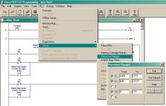
The retenitave memory ranges can be adjusted/setup by the user as follows:

retenitive ranges..jpg
 
You do make some very good points.

I'm pretty sure that I've used a different PLC type that had the retentive and non-retentive memory areas too (I believe it was GE Fanuc, but it may have been Mitsubishi A series) I'll have to go back and look at the manuals tomorrow to see.

Maybe someone else knows.
 

Similar Topics

Hi everyone, new to forum. Since very long time i having issue with 1734-AENT module, after some period of time its keep stuck in error (simmilar...
Replies
2
Views
127
Hello, I am new here. I am trying to find good places to sell some surplus items that I have that isnt through ebay. Does anyone have any sources...
Replies
5
Views
319
Hi all, installed on chassis A17 an A/I from Allen-Bradley , problem is what ever I do , all channels are sticked on value 39.9 and cannot change...
Replies
1
Views
116
I have a 1769-L24ER-BB1B and I am trying to flash it to 34xx, its flashing red and faulted, when I try to flash it I get a popup stating it needs...
Replies
14
Views
240
I have a client who periodically experiences network communication issues. Sometimes when I VPN into the site, their SCADA systems will flash comm...
Replies
2
Views
158
Back
Top Bottom