Reverse Tunning in Micrologix

Rehu09

Member
Join Date
Nov 2017
Location
USA
Posts
64
Hello all,

I have transmitter as Process Variable which basically gives 4-20ma. I need to make CV as 100-0
For 4ma it needs give 100
for 20ma it needs give 0
How can I tune P&ID? Can I give Gain in negative to work
KC=-0.1
KI=?
Kd=?
 
What model is your Micrologix?

It should support the SCP instruction which can let you take the raw analog values and rescale and invert the slope all in one easy to understand instruction.

For use with a PID, I normally will use multiple SCP instructions. I will scale the raw signals to engineering units first, then SCP the engineering value to numbers scaled for PID in separate instructions. The range for PID values in a Micrologix is normally 0 to 16383 for the process variable, setpoint, and control variable. SO, the setpoint will be entered in engineering units and also scaled for PID with the SCP instruction and the control variable will be scaled from PID units to engineering units before being sent to another SCP block which scales it once again to match the requirements of an analog output card. This might seem like a lot of extra steps, and it is, but it is almost always useful (or necessary) to have the values available in the PLC in engineering units for other logic or for visualization.
 
Last edited:
What model is your Micrologix?

It should support the SCP instruction which can let you take the raw analog values and rescale and invert the slope all in one easy to understand instruction.

For use with a PID, I normally will use multiple SCP instructions. I will scale the raw signals to engineering units first, then SCP the engineering value to numbers scaled for PID in separate instructions. The range for PID values in a Micrologix is normally 0 to 16383 for the process variable, setpoint, and control variable. SO, the setpoint will be entered in engineering units and also scaled for PID with the SCP instruction and the control variable will be scaled from PID units to engineering units before being sent to another SCP block which scales it once again to match the requirements of an analog output card. This might seem like a lot of extra steps, and it is, but it is almost always useful (or necessary) to have the values available in the PLC in engineering units for other logic or for visualization.
Thanks for quick response, Im using micrologix 1400
I understood the process of SCP insturction which we do basicallly 4-20ma to 0-16383 and then use the same as processs variable in p&id block. CV of p&id block needs to again scaled to 0-16383 then SCP 0-16383 to 4000 to 20000 basically for the actuator

my question is how can I tune the P&ID block to get reverse tuning
example for 4ma I need to get the valve completely closed 100% closed and for 20ma it needs to open completely which means 0%
 
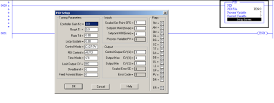
Change the control mode to suit your application.

Direct acting -> CV will increase when PV > SP
Reverse acting -> CV will increase when PV < SP
 
Last edited:
If you are using the PID control block, double click on setup screen and you'll see control mode on the left side.

pid.png
 

Similar Topics

Hi all, I'm having trouble solving a problem I've been working on for several months, and thought you might like a stab at it. The machine runs...
Replies
22
Views
920
I have a SX2 plc and i'm getting 0-10v analog signal,but i need 10bar analog output in 0v can someone explain how its done
Replies
2
Views
534
I'm trying to add on to a safety circuit and trying to make sure this is fail-safe. My safety scanner needs some muting when things aren't running...
Replies
8
Views
800
Hi, I have issue with acs800 starting the motor in reverse for like 5-6 seconds with a max speed of around -220 rpm before it goes to the...
Replies
10
Views
1,984
I am looking at a 1305 drive connected to a PLC5 via RIO. The drive is working and I was able to get a functional HIM working on the drive as...
Replies
3
Views
1,845
Back
Top Bottom