1746-HSCE in Sequencer Mode

glaverty

Member
Join Date
Apr 2002
Location
Parts Unknown
Posts
509
As some of you may recall from a few of my previous posts I have been working on a project with an SLC5/02 and a 1746-HSCE in sequencer mode. I've been trying to figure out how this thing works for a while now and have come to a problem that I just cannot figure out.
So I thought I would post my problem here and see if you any of you can help me out.

Basically the machine cuts sheets of metal to length and punches some holes in them.

The operator chooses which type of band he wants the machine to run through a panelview 550.

Depending on which Band the operator chooses determines a different N File which gets loaded into the high speed counter file MO:6.0.

The problem that I am having is that after going through all the N files for the different parts it seems as if the sequence is missing a set of punches for all the band types. But I have seen the machine run and it punches all the holes it is supposed to so I must be missing something. The files I am using are right out of the machine so I know they are the correct ones.

A sequence basically looks like this

Slow clutch
Brake, Punch 1, Punch 2
Fast Clutch
Slow Clutch
Brake, Shear
Fast Clutch
Slow Clutch
Brake, Punch 3
Fast Clutch
Slow Clutch
Brake

Once the sequence reaches the point where only the brake is on the high speed counter is reset and the process starts all over again.

A finished part will have two holes punched on each of its ends and one hole somewhere between the other two sets but not centered.

Going through the sequence I see how the first set of two holes is punched and the hole in the middle but I don't see how the second set of two holes gets punched.

I am attaching a Zip file with 3 files. Two of the files are gifs, one shows what a finished part looks like and the other shows the layout of the punches, shear, and encoder on the machine. The third file is an excel spreadsheet which I created which breaks up the N files which get loaded into the high speed counter. I will be writing a second post in order to upload the RSLogix program itself.

I realize this is a lot of information for anyone to go through in order to help me but any help will be EXTREMELY appreciated.
 
I just wanted to make a couple of points about what you posted...

The first is regarding your naming convention...

Slow clutch
Brake, Punch 1, Punch 2
Fast Clutch
Slow Clutch
Brake, Shear
Fast Clutch
Slow Clutch
Brake, Punch 3
Fast Clutch
Slow Clutch
Brake

I would have used the following names...

Engage Slow clutch
Engage Brake, Do Punch 1, Do Punch 2
Engage Fast Clutch
Engage Slow Clutch
Engage Brake, Do Shear
Engage Fast Clutch
Engage Slow Clutch
Engage Brake, Do Punch 3
Engage Fast Clutch
Engage Slow Clutch
Engage Brake

Now, I'd like to comment on your sequence...
(no, I didn't look at your zip file)
Seems to me it should be something like...

(I assume the process is started manually when a piece is in place...???)

Release Brake
delay
Engage Slow Clutch
wait for???
Release Slow Clutch
delay
Engage Brake
delay
Do Punch 1
delay or wait for "Punch-1 just got back Up" (NOT "IS UP")
delay???? no movement here?
Do Punch 2
delay or wait for "Punch-2 just got back Up" (NOT "IS UP")
Release Brake
delay
Engage Fast Clutch
wait for???
delay
Release Fast Clutch
delay
Engage Slow Clutch
wait for???
Release Slow Clutch
delay
Engage Break
delay
Do Shear
delay or wait for "Shear just got back Up" (NOT "IS UP")
Release Brake
delay
Engage Fast Clutch
delay or wait for ???
Release Fast Clutch
delay
Engage Slow Clutch
delay or wait for ???
Release Slow Clutch
delay
Engage Brake
delay
Do Punch 3
delay or wait for "Punch-3 just got back Up" (NOT "IS UP")
Release Brake
delay
Engage Fast Clutch
delay or wait for ???
Release Fast Clutch
delay
Engage Slow Clutch
delay or wait for ???
Release Slow Clutch
delay
Engage Brake

END OF SEQUENCE

All of the delays are for the purpose of preventing the Brake, Slow Clutch and Fast Clutch from being engaged at the same time. Using the delays will extend the lives of your clutches.

This exercise also points out that a sequence usually contains a hell of a lot more steps than you might think on first thought!
 
Terry,

You make some good points.

The program does have delays to allow for motion to stop they are all carried out in the Ladder Logic. The Sequencer routine in the High Speed counter is turning bits on or off but they are not directly firing the outputs so there are delays in place to prevent needless wear and tear on the machine.

The steel is fed off of a large roll so there is no handling of the part before it goes through the machine.

I agree that there is a lot more to the sequence in reality. What I wrote is strictly what the sequencer is doing, what it looks like when you read the MO file. What you wrote is the combination of the High Speed counter sequence and the Ladder Logic together.

My problem is that together(the sequence with the Ladder Logic) or seperately I don't see how this sequence is working the way it is.
 
So... I gather from your spread-sheet and your final-product picture that we are only looking at "CH-24", "CH-36" and "CH-48".

Maybe you could define what the columns represent? Some are obvious and some are not.

Also, on your final-product picture, can you identify which holes are produced by what "Punch-#". The direction of flow would also be nice.

Could you also give a little description about how your encoder data is used?

From your description and looking at the punch drawing, something just doesn't jive!

If the "shear" is supposed to happen at 1-inch after one of those punches operates... I just don't see it happening in your drawing!


I could see it working like so...
(Assuming that "Punch-1" & "Punch-2" produce the 2-side-by-side holes, and "Punch-3" produces the single hole)

----> FLOW

Encoder----->Punch-1&2----->Punch-3----->Shear

Seems to me that the Encoder needs to be on the INFEED END - not in the middle.

QUESTION:
With your current setup... is the first piece garbage? Seems, if it does work - somehow- then the first piece must be garbage.

WHAT IS WRONG WITH YOUR PICTURE??????
 
Terry,

Thanks for taking the time to look at this stuff I really appreciate it. Sorry that my information wasn’t as descriptive as it should be.

First off let me make this clear, this machine is built and has been running since some time in the 80’s. The layout of the shear, encoder and punches is the way the machine is actually built. They select which piece they want to make from a menu and the PLC then loads the parameters into the High Speed Counter. What they want me to do is modify the program to allow them to make custom parts with anywhere from zero holes to 16 holes.

What I am trying to do now is determine how this thing is working when they select one of these pieces from the menu so I can come up with an algorithm to build the sequence profile from data they will input for a custom part.

So... I gather from your spread-sheet and your final-product picture that we are only looking at "CH-24", "CH-36" and "CH-48".

The reason there are numbers for CH-24, CH-36, and CH-48 is because those are parts that I have actual dimensions for therefore I am using them as examples in trying to figure out how this thing works.

Maybe you could define what the columns represent? Some are obvious and some are not.

In the Excel file the tab labeled “Standard Parts Files” is a breakdown of the N files for each of the parts. I obtained the breakdown from the HSCE user manual which you can find here http://www.ab.com/manuals/io/1746/174665.pdf if you want to look at it.

The first column in this table is a description of the byte of data, the next is the byte number. The fourth column contains the value in decimal. The next four contain the value in binary so as to see what each one means. I added comments to the two rows above the columns in binary to explain what they do. The top one only refers to Rows 9-20. These rows contain the output state for each step in the sequence. The bottom one just refers to the bits in each column.

The tab labeled “Standard Part Step Values” is a breakdown of each step, the number of counts that each step occurs at, the outputs that are on for that step and the action of those outputs.

On the parts the I have dimensions for I added two other columns. The first one takes the number of counts and multiplies it by the distance each count is equal to (0.0060002”).
The next column adds up the total distance the piece has been moved. You have to be careful when looking at this column and the one before it because the encoder resets to zero every 2000 counts. I have no idea why they chose 2000.

I know it is rather confusing, I’ve been looking at it for a few weeks now so it makes sense to me, I hope my explanation is sufficient.

Also, on your final-product picture, can you identify which holes are produced by what "Punch-#". The direction of flow would also be nice.

I’m uploading some new drawings with the things you asked for. Let me try to describe the sequence the way I have seen it. Unfortunately I have only seen the machine run once.

The operator chooses the part he wants to run through the oit and starts up the machine

This it what it looked like was happening to me:

1. Do Punch 1 and Punch 2 (punch two holes in the part)
2. Index part 2 inches
3. Do Punch 1 and Punch 2 (punches two more holes in the part)
4. Machine indexes so the 4 holes are centered under the shear( index distance = punch1/punch 2 distance to shear – 1”)
5. Do Shear (You now have two pieces the end of the last one and the beginning of the second or current part. This is how you get the 1 inch from the edge to the first holes and last holes)
6. Index part
7. Do Punch 3
8. Index Part
9. Start over at Step 1

Could you also give a little description about how your encoder data is used?

Each count of the encoder is equal to 0.0060002 inches. I multiplied this by the number of counts to get the distances. The High Speed counter monitors the counts when a value is reached where it needs to do something it does it.

From your description and looking at the punch drawing, something just doesn't jive!

For the most part the sequence is making sense if you can follow all this information I am giving you. I just don’t see how the last set of holes gets into the part because once the brake is on by itself(the last step in the sequence) the ladder logic resets the sequencer.


If the "shear" is supposed to happen at 1-inch after one of those punches operates... I just don't see it happening in your drawing!

Let me try to explain this to you better.

Look at the “Standard Part Step Values” tab and part CH-24

Punch1/Punch2 occurs at 1.75206” the part is then indexed 16.32654”(18.07860 – 1.75206) placing the two holes 1” before the shear(they have not passed under the shear yet)

To check this take the shear to encoder distance(8.5”) and Punch1/Punch2 to encoder distance (8.90”) add them together and subtract 1”

8.5” + 8.90” = 17.4” – 1” = 16.4”

Not exact but close enough for figuring this thing out.


I could see it working like so...
(Assuming that "Punch-1" & "Punch-2" produce the 2-side-by-side holes, and "Punch-3" produces the single hole)

----> FLOW

Encoder----->Punch-1&2----->Punch-3----->Shear

Yes Punch1/Punch2 produce the two side by side holes and punch3 produces the single hole.

Seems to me that the Encoder needs to be on the INFEED END - not in the middle.

Does it really matter where the encoder is? They are offsetting all the data for instance if you look at the excel file tab “Standard Part Step Values” CH-24 and take the distance between Punch1/Punch2 and Punch3 you get:

45.91353” – 1.75206” = 44.16147”

now add 7.28” which is the offset of Punch1/Punch2 to Punch3(this can be seen in the layout of the shear, encoder and punches)

44.16147” + 7.28” = 51.44147”

This is approximately the distance from Punch1/Punch2 to Punch3 that can be seen in the drawing of the part.

It’s all just a matter of relation to each other. Basically you have to take into account the distance your moving from the action you just did plus or minus the offset of the next actions location.

QUESTION:
With your current setup... is the first piece garbage? Seems, if it does work - somehow- then the first piece must be garbage.

Like I said I have only seen it run once and they had already had the machine going so I’m not sure what the deal is with the first part. I would think however that if material is under the encoder and you start at the beginning of the sequence when the fist piece is cut you would just get a small hunk of wasted steel.
 
OK,

Here's my take on what's happening...

I can't read an RSS File. But, I'll bet, that somewhere in the ladder, the code causes the sequencer to reset to restart after the first double-punch is made.

The metal does not start at the punch-point. It starts at the last break-point in the sequencer - a short distance from the next double-punch point.

1. Index a small amount
2. Punch the LAST pair of holes on the previous piece.
3. Reset Sequener to start from step-1 (or maybe step-2??)
4. Index 2"
5. Repeat step-2 to Punch the FIRST set of holes on the next piece.
6. Index about 28"
7. Punch Center hole
8. Index 26.7" Brake ON - Metal is almost at point for next Punch.
Return to Step-1, and continue.

Seems that the process Begins with the Last Step on the previous piece. That is, when an operator starts the process in the morning, he starts by finishing the piece that was not finished last night!

The key is the Sequencer Reset after makin the First Pair of punches.

If the system starts with no material in it, this setup will produce garbage on the first cycle. The system won't have an encoder count until the metal is under the encoder and can cause the encoder value to change.

Then when the system is started, it moves a small amount and punches the LAST set of holes in the garbage piece. It's my guess that they end-up with a 9" piece of garbage when they start-up an empty machine.

If the encoder was on the Infeed End, there would be no waste.

Now, another thought just occurred to me... it could be that the leading edge of the initial piece might not be square... in that case, the waste might be acceptable.

So... that's my shot. What do you think?
 
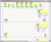
I thought the same thing when I first started looking at this. But looking at the Ladder logic I don't see that scenario taking place either. I’m posting a picture of the reset sequence from the ladder logic.

Notes:

I:6/72 = I:6.4/8 - Punch 1
I:6/73 = I:6.4/9 - Punch 2
I:6/74 = I:6.4/10 - Punch 3
I:6/75 = I:6.4/11 - Punch 4 (No longer connected)

Looking at the ladder logic and looking at the sequence breakdown in the excel file it doesn't look like it can ever reset at any time other than when the brake is on by itself.

I must be missing something.

seq3.gif
 
First, I gotta ask... did you build that Excel Sheet?

In the Excel listing, for CH-24, I see Step-2 turning ON the Brake, executing Punch-1 and Punch-2.

In the ladder you just displayed, I see "NOT Reset Punch-1" and "NOT Reset Punch-2" and "NOT Reset Punch-3".

I don't know what the rest of the code looks like, but, if "Reset Punch-1" and "Reset Punch-2" are bits that turn ON IMMEDIATELY at Step-2, and then, PUNCH-1 and PUNCH-2 are subject to a timer, after which, those bits cause the punches to retract and then those same bits go OFF, then you have the necessary condition to activate the RESET TIMER just after Step-2 is completed.

If you find it is that way, then I can only say, that's one $hitty piece of code!

This is a prime example of "How not to code".

Somebody tried to be "cute" and use one timer for...
"Reset After First Punch"
which is actually the final punch of the previous piece...
AND
"Reset After Step-16"
which the actual end of the specified sequence.

I suggest you investigate how "CR-10 RESET", "CR-11 RESET", and "CR-12 RESET" are generated, how they are controlled, and when they actually go OFF.
 
Terry Woods said:
If you find it is that way, then I can only say, that's one $hitty piece of code!

This is a prime example of "How not to code"
Trust me Terry, you DON'T want to see the rest of this program... It's a mess!... :rolleyes:

Which reminds me to mention... Glaverty, once you figure out how the system works (or even if you don't!), do yourself a favor and re-write the program from scratch...

beerchug

-Eric
 
Terry,

I think you might be onto something there. I'm going to check that theory out and I'll let you know what I figure out. I guess I wasn't thinking "outside the box" enough because I never would have done it like that.

Eric,

That isn't even the entire program, there are 400+ more lines of mayhem in that thing.

Thanks guys.
 
glaverty said:
...there are 400+ more lines of mayhem in that thing...
Yes, "Mayhem" is an excellent term for it... :D

Since the original programmer doesn't seem to have a clue (going by his organizational skills), I doubt there's anything special going on in the program. IOW, it looks to me like he:

1.) Wrote a program that he thought would work
2.) Realized that it didn't work as planned
3.) Kept adding "patch" after "patch" until it worked "good enough"
4.) Left you with the mess he created

Just take what you've learned so far and write your own program. During scheduled downtime of the machine, stick your new program in and test it. If it doesn't work, you can always reload the original (so the machine can run) while you make additional changes to your new program, and continue testing at each scheduled downtime.

beerchug

-Eric
 
Got It

It was right there on the Excel sheet the entire time and I didn't catch it. Makes me angry, live and learn.

If you look at the excel sheet and the row that says "Initial Outputs/valid steps 17-24" you'll notice that the initial outputs are bits 8,9,12 which corresponds to the brake, Punch 1 and Punch 2.

So once the brake is on by itself the sequencer resets the initial outputs are then activated and Punch 1 and Punch 2 are actuated. So the last set of holes on the piece are actually the first set of holes for the sequence. Makes perfect sense.

Not the most straight forward way of doing things but I guess it works.

Terry thanks for taking the time to look at this I really appreciate it.
 
Last edited:
3dd1cb476424a1d8.gif


Glad to have banged yer ol' noggin around a bit to help you find it on your own.

What I have seen of the code sure looks like ****. And I believe Eric when he says the rest of the code is too.

Depending on your particular engagement with this project, you sure might consider trashing the program and starting from scratch. It's a simple program and does not need to be that confusing.

If you can do so, then I suggest that you do. If the machine ends up operating any better... well, who will they call next time?
 
Well the noggin definately needed a good whack.

I'm seriously considering rewriting the entire thing. I won't get anymore money but it sure will look better and I'm sure it will run better in the end as well and its a good learning experience. That was part of the reason I took the job in the first place, to get some AB experience.
 

Similar Topics

I had a 1746-HSCE go suspected bad. have to swap the card in the morning. Other than dip switch settings is there any configuration to do?
Replies
1
Views
1,022
Hi there, I have a machine where was a servo with extra encoder. That encoder had resolution 100ppr/5V. We did replace complet servopack (...
Replies
0
Views
947
I have a SLC 5/05 processor and I am trying to reference an output from a High speed counter card to be used elsewhere in the PLC. The output...
Replies
1
Views
1,637
I am upgrading HSC modules and have some questions. I can't attach the manuals for reference as they are too large. 1746-HSCE uses M0:e.1/4 for a...
Replies
0
Views
1,648
Processor Error Message: G file configuration error.. user program G file size exceeds capacity of the module. I cannot seem to find any data...
Replies
3
Views
2,032
Back
Top Bottom