Load cell scale using leverage

grnick50

Lifetime Supporting Member
Join Date
Nov 2010
Location
Ptolemaida
Posts
332
Dear all,

I am upgrading the control system of an old asphalt plant and I am phasing the following issue.
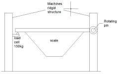
Two of its scales do not have 3 or 4 load cells at each corner of the scale as usual but it uses a lever principle instead.
From one side of the scale there is a pin welded to the frame of the machine. The other side of the scale is resting on a "knife" shaped beam that is attached to a 150kg beam type load cell.
The maximum weight that ever goes to the scale is 1500kg.
The problem is that there is no way to find out what is the maximum of the scale. In other words what coresponds to the 150kg. There is no drawings of the geometry of the scale to calculate the leverage, nor there is a way to get info from the current obsolete control system.

The new weight transmitter that goes in has the option to apply a known weight on the scale and then enter that value to the transmitter and let it do the maths.
I am wondering if anyone has experience from a similar case and if there is a better solution as I am afraid of non - linearities. Also, to do the calibrattion as mentioned above, requires a large amount of approved weight samples and that is sort of an issue.

Regards
 
I think the most you want in there is 300kg. including the scale

If not, someone will correct me and we'll get this discussion moving

BTW I never heard of Ptolemaida ... I looked it up ... it looks beautiful
 
Last edited:
If the load is always centered on the platform the load cell will read 50% of the total weight. Otherwise there is no way of knowing.

Newton's laws dictate that the sum of all forces must = zero, so the total wight on the platform equals the sum of the force at the load cell and the force at the pin. However, the sum of moments (torques) around the pin must also equal zero. M = F x d, so the closer the weight is to the pin the less proportion of load will be supported by the load cell.

An introductory statics text will explain it, but here is a start: http://www.engineeringtoolbox.com/beams-support-forces-d_1311.html
 
That 150 kg loadcell cannot be used like this to weigh 1500 kg plus the weight of the scale itself. No matter if it only weighs 50% of the scale. Something is totally wrong.

When you do have a suitable loadcell (my guess, must be rated for 1000 kg), then you can calibrate it like this:
Load the scale with whatever is "full" with the material you normally use and in the way you normally do it.
Offload the scale into another container, and then weigh this container on another scale that is already calibrated.
Load the un-calibrated scale again with the (now known) amount of material.
Use the value obtained from the calibrated scale to calibrate the load cell converter on the uncalibrated scale.

If anything changes in the loading process (type of material, method of filling, ...) you have to repeat, or accept that the scale is not accurate.
 
vehicle-scales
I think the lever system is more complicated as depicted by you.
You will need to know the tarra (so the weight of an empty scale)
and how much you can fill the scale.
This added will give you maximum weight.
If the cell is 150 kg you could use a simple peopleweigher to get the numbers you need.
put it in place and stand on the scale, and see the display.
 
Hello all,

After spending a day at site and having a better look in the scale I realized that it is not as simple as shown in the sketch. If it where like that I agree with Tom that I would get half the weight.
The scale has a complex system of three levers that reduce the force applied on the load cell. I did get some sample weights and I did calibrate the scale by applying a known weight and setting that value to the transmitter. The result was great. I will repeat the calibration with more sample weights next week.

That system is built in the 70s from an Austrian company called Wibau. It used to have a potentiometer system that was replaced with the 150kg loadcell in the 90s. It operates since then with a loadcell with that rating loading 1500kg batches.
If thi machine was built today it would probably have the scale supported by three load cells without any levers.
From what I have seen today however I have to say that it is a very well designed scale for the way it operates. From cost point of view nowadays I dont see a point for building a system like that.

Regards

I used to work for a scale company in the '80s. Anytime the question of the lever ratio from the scale deck to the scale indicator came in question, we had a simple test.

A spring scale was used to hang the lever to the scale indicator and a known amount of weights were placed on the scale. The actual weight/spring weight change of weight equaled the lever ratio.
 
curlyandshemp is bang on for calculating the mechanical advantage. But remember, just because it has a 150lbs loadcell doesn't mean the system can handle that much. It may have been the only load cell available at the time.

The mechanical lever scale is very accurate. Most used to connect the final lever directly to a dial to show the weight. Most of the ones I work on have been retrofitted to a loadcell like yours has.

If you are seeing problems with linearity it is most likely the bearings. (Not the typical rolling bearing, but the knife edge you described.) You can always jack up the beams, remove the knife and sharpen.
 

Similar Topics

Good Afternoon, I’m limited with a skilled maintenance staff to design and build Load Cell , Rollers , etc. for conveyor sections . Do...
Replies
11
Views
651
Good Afternoon , Does Rockwell Automation have an Input Card , maybe in the 1734 series , or CompactLogix series that will receive signals...
Replies
15
Views
804
Can someone recommend an Intrinsically safe barrier that can be used with an "ANALOG" load cell on a weigh scale? Load Cell is rated to be in a...
Replies
4
Views
1,360
Hello All, I have two bags of two different types of peanuts hanging on a load cell above two separate feeders. I am using Studio 5000 and would...
Replies
45
Views
8,819
We have a web converting process that involves the web passing over rollers with load cells on each end. This provides a tension readout from an...
Replies
5
Views
2,469
Back
Top Bottom