MSG Instruction Help ControlLogix to Micrologix

A nitpick; the sub-elements of a DINT or INT are bits, but they are not BOOL datatypes. Both a bit sub-element and a BOOL element are a way of representing a single bit of data, but they are not completely interchangeable.

What you have will work, but it would be easier to have a single INT tag called PhotoeyesStatus, rather than a 1-element array. Having an array with length of 1 is technically allowed but is a little confusing.

If it were me, I would make an INT array tag that is several words in length (like PE_Status_Data[8] ) and transmit that, so that I have extra data for future use. When you're transmitting over Ethernet, the amount of data payload has almost no effect on the time or resources required to move the data.

In particular, I like to transmit one extra word with a value that increments every second or so. That way the receiving device can tell if the transmissions are still arriving and can take action if they stop.
 
If it were me, I would make an INT array tag that is several words in length (like PE_Status_Data[8] ) and transmit that, so that I have extra data for future use. When you're transmitting over Ethernet, the amount of data payload has almost no effect on the time or resources required to move the data.

So i can make the tag "PhotoEyeStatus" an INT and give it lets say 10 arrays "PhotoeyeStatus[0]-[9]" and change the number of elements to 10 and type in "PhotoEyeStatus" as the source element? Then that will transmit to the micrologix?
 
Make the source tag a tag named PhotoeyeStatus, with a data type of "INT[10]".

In the MSG instruction, the first element of the array will be your Source tag, " PhotoeyeStatus[0] ". You can actually refer to the whole tag name as "PhotoeyeStatus" and it will infer Element 0, but I prefer being explicit.

Make the Number of Elements 10
Make the Destination Element N50:0

That will transfer

PhotoeyeStatus[0] -> N50:0
PhotoeyeStatus[1] -> N50:1
PhotoeyeStatus[2] -> N50:2
PhotoeyeStatus[3] -> N50:3
PhotoeyeStatus[4] -> N50:4
PhotoeyeStatus[5] -> N50:5
PhotoeyeStatus[6] -> N50:6
PhotoeyeStatus[7] -> N50:7
PhotoeyeStatus[8] -> N50:8
PhotoeyeStatus[9] -> N50:9
 
Remember also that MSG instructions execute only on a false-true transition of their rung.

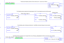
I like to use a self-resetting Timer to send the MSG only every few milliseconds, and an XIO instruction for the .EN bit of the MSG control tag to prevent filling up the buffer if the MSG has not completed.

Screenshot example:

(error noted; the watchdog will only ever be between 1 and 9998. Details, details....)

MSG_with_Watchdog.PNG
 
Okay so I have both the micrologix and compactlogix online and I see both through my switch in rslinx. In my message configuration I have a error code of 16#0001 and extended error code 16#0007_0311. In my communications tab I have 1, 192.168.1.1 and I have tried 2, 192.168.1.1 also with no luck. The micrologix IP is 192.168.1.1 and compact Logix is 192.168.1.15. Any ideas?
 
I figured it out. I needed to put 1, 1, 2, 192.168.1.1. (1,1,2) is displayed as LocalENB,2. That’s for a ControlLogix 1769-L23E L32E and L35E just in case anybody is wondering lol
 
Ah... my bad information ! You even told me it was a 1769-L32E.

Yes, the older CompactLogix used a "virtual backplane object" with a logically separate Ethernet daughtercard in Slot 1.

The modern 1769-L30ER or similar controllers would go directly to Port 2.

The older ones, as you pointed out, need to go "backplane (1), Slot (1), Network (2), IP".
 
That’s okay I just did a little searching through the forums and found it. It makes sense though. When I finally did get the two controllers to communicate information it shoved the “Photoeye” tag data into N50:0 in decimal form. When I switched it from decimal to binary 0-15 is when I saw the 0’s and 1’s from the control Logix processor. I thought for sure it would shove information into N50:0-15?
 
It’s odd. The integer N50:0 displayed a value of 112. The rest of the integers were 0’s. The tag “Photoeyes” sub elements started with a 1,1,0,1,1 exc. So shouldn’t that be
N50:0 (1)
N50:1 (1)
N50:2 (0)
N50:3 (1)
N50:4 (1)
 
Nope. All 16 bits in Photoeye_Status[0] were written into N50:0 together. Both use 16 bits to store an integer value.

N50:0 = 112 (decimal)
N50:0 = 70 (hexadecimal)
N50:0 = 0111 0000 (binary)

N50:0/0 = 0
N50:0/1 = 0
N50:0/2 = 0
N50:0/3 = 0
N50:0/4 = 1
N50:0/5 = 1
N50:0/6 = 1
N50:0/7 = 0
 
I have a problem. I can't communicate L81 control logix redundant controller with Micrologix PLC.
L8x Redundancy does not support any legacy communications, including Micrologix PLC
 

Similar Topics

Hello All, This might be a simple question for most of you. I am working on performing some tests on an EIP device through RSLogix 5000. Based...
Replies
7
Views
2,028
Hi, I'm trying to ensure I have the correct path to allow msg read from 5380 processor via compactlogix. The SI has installed it in a way I'm not...
Replies
12
Views
6,482
I'm trying to use a MSG instruction to get data from a SLC into a ControlLogix. I want to read some Boolean tags from the SLC. Is it possible to...
Replies
4
Views
2,847
Good morning everyone. I'm relatively new to the Allen-Bradley world. My issue I'm facing is this. I have a remote Refractive Index sensor...
Replies
2
Views
2,245
The good news is I became a dad today, i'm posting from the hospital at this moment. the bad news is i've still not figured out reading my...
Replies
19
Views
5,103
Back
Top Bottom