GT Designer3: creating a water flow controller

Mas01

Member
Join Date
Oct 2020
Location
Leicester, England
Posts
1,105
D9Zf7oncze7GgAAAABJRU5ErkJggg==
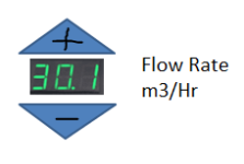
I'm looking for some general guidance on creating a flow meter controller in GTDesigner3. The pump supplier said that the inverter can be connected and controlled at the PLC. To this end, I want to create a thing like this in Designer3 where flow rate can be adjusted (for example in increments of +/- 0.5 meters cubed/hour. Can anyone offer any suggestions?I realise that the display will need to be linked to a parameter e.g. D100.
EDIT - just realised the push-buttons need to be "momentary contact" style.
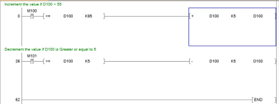
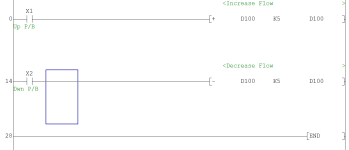
I think the code will look something like this.
Capture.PNG Capture2.PNG
 
Last edited:
First of all, you will not use X inputs for the bits in the PLC if using touch buttons on the HMI, these will need to be "M" bits.
These bits in the PLC also need to be one shot or you will get increments of multiple values i.e. if adding 5 every push because the PLC Scan may be very short compared to the on time of the bit you could increment more than once.
So it would be best to use the pulse function (that is the N/O relay contact with an UP arrow in it).
Also you need to check for min or max values for example you need comparisons so that the down operation will not go below zero i.e. negative or above your max limit.
The lower & upper limit is what you require and the amount you increment i.e. it could be 1 (0.1 Assumes decimal not float so 1.0 is actually 10) .

Inc_Dec.png
 
Last edited:
Ah yes, 'M bit" is what I need. I recognise it from other pushbuttons on the PLC at work.
And yes, I forgot about the max and min values.

Many thanks.
 
You don't actually need push buttons you could just use an input field to allow the operator to enter the value, this could be an integer (displayed as a float) so 3.5 will = 35 as integer then you will not need the spin buttons or code in plc.
You can set limits on what can be entered and password etc on the HMI.
Assume you are outputting this to an analogue just scale it up from 0-100 (or what ever your setting is) to the scale required for analogue output i.e. 0-2000
 
Would the flow rate be an analogue input or an analogue output?
If the PLC were just displaying the flow rate, that would be an AI (presumably), but as I'm adjusting it Up/down does it need to be analogue output?
I'm trying to determine what type of PLC card it needs connecting to.
 
Assuming you want to control it then yes it would need to send it out on an analogue output to a VFD. so for example, you have a VFD that is controlled from a 4-20ma from the PLC, your field can be adjusted we will say for 0-10 metres cubed per hour. the VFD would go from 0-50 Hz so assuming you want to alter the feed rate between 3-10 cm/h then your value will be adjustable from 3.0 to 10.0 (30 to 100 as an integer). then you need to scale this up so assume the analogue card requires a digital value of 0-2000 for 4-20ma then do the scaling in reverse as per the scaling of the analogue input.
So multiply the cm/h by 20 so at 5.0 cm/h = 1000 (12ma out of analogue card).
It will depend on the resolution you require i.e. 0.1 Cm/h or a higher one 0.01).
You will need to calibrate it somehow. i.e. run it at top speed for say a minute and weigh it. We used to do this on a rice process where the rice was fed continuously into a cooker, hot water & steam was injected as the rice moved along, perfect rice once calibrated, however, there was a lot of variables, rice Kg per hour, residence time, hot water addition in Kg/h, steam at Kg/h & auger speed.
Brilliant, many thanks again for your input.
Cooking rice... interesting application!
 
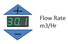
Does anyone know the correct symbol/shape in DESIGNER3 to create triangles - something like this?

The digital display itself is not the problem.

However, I tried looking for triangular buttons on the menu down the RHS, but couldn't find anything. In the end, I had to make a freehand sketch using the polygon tool. Then I assigned 'lamp properties' to the shapes and defined a device name to each.

Capture.PNG
 
Last edited:
Look at FA Metal Switch A2 under search by function you can add on top some text.
Edit: forgot to mention the text is a comment field not a text field, just associate a bit to the button.

Button.jpg
 
Last edited:
Look at FA Metal Switch A2 under search by function you can add on top some text.
Edit: forgot to mention the text is a comment field not a text field, just associate a bit to the button.
Can't seem to find the LIBRARY window on my GTDesigner3...is it available from the main menu?
 
Assuming you want to control it then yes it would need to send it out on an analogue output to a VFD.
I'm a bit confused by this: if I am controlling the flow from the PLC, I send the flow demand out on an analogue output card, but the confusing thing is...to actually read the value from the VFD in the first place, does it need connecting to an analogue input card?

There seems to be a conflict here (AO vs AI card).

Hope you understand my question.
 
Last edited:
You don't read the flow from VFD you need a flow meter in the line and read that, Flow meters often have two outputs one digital that give pulses per litre/gallon or whatever and an analogue to measure the flow rate.
In saying that you could just set the flow based on the frequency of the inverter in other words at 50hz (say 20ma) the pump will deliver x cm/min. however this is not an accurate way of doing it but if you only need a rough flow rate you do not need the feedback from a flow meter. To be honest. it probably would give you a +- 10% accuracy providing you calibrate it but that is not easy. Using a flow meter is the best way and the inclusion of a PID loop within the PLC will ensure it stays within it's limits and smooth out any variations due to back pressure etc. So for accuracy then you need both analogue input & output. I have seen water supplies that do not use feedback from some type of flow sensor, a positive displacement pump will give reasonable flow rates based on speed but it will probably not be linear.
 
We are getting one of these for work - a Danfoss inverter fc 102.
The technical rep said it has a panel where we can connect wires to the PLC so we can control the water flow, but I've not yet seen the datasheet or whatever that defines the terminals/signals at the inverter end.
Ah!!! The penny's dropped. Yes, we do have a flow meter in the line! I'm being a bit dense! It's been connected for a while and is already displayed on the PLC.
 
Last edited:
The Danfoss inverter will not give you the flow rate only the speed of the drive. To measure the flow you will need a flow meter. What he is talking about is an analogue input on the inverter to control it's speed from a signal source i.e. a 0-10v / 4-20ma or 0-20ma. and possibly an analogue output to read back the speed (frequency) the drive is running at. A VFD cannot measure flow on it's own.
Also the Danfoss 102 is designed for HVAC (heating & Ventilation) no idea why he is recommending that. I don't think you have supplied the right information on what you are trying to do, that type of control is for closed loop control of HVAC it will work but you still need some form of measuring the flow in the pipe.
 

Similar Topics

I'm using a GT1275 HMI with GTDesigner3 and am trying to add some Alarm Logging capabilities. I've made an alarm page and have it working...
Replies
2
Views
437
Context: Mitsubishi GX Developer/GT Designer 3. At the moment on our PLC's HMI (GT Designer 3), pressing any of the SCREEN buttons will navigate...
Replies
7
Views
1,868
In GT designer 3, the rig operator wants me to display a text string on the screen when a bit goes TRUE, and make it disappear when the bit goes...
Replies
5
Views
1,881
Hello! I keep getting an error when trying to open a HMI in GT Designer 3. I go to Project->Open then select my project (GOT Type GS21**-W) and...
Replies
4
Views
2,811
In the GT designer 3 project the time looks correct, but when Iake the project "live" it's 1 hour behind. What's makes it more odd is that when...
Replies
7
Views
2,751
Back
Top Bottom