GT Designer3: creating a water flow controller

My mistake, I think it's an FC 202 (if that makes a difference).
Yes, we have a separate water flow meter in the cooling water system. It's a GE unit I think.
Yes, the rep said the inverter needs a 4-20mA input, I remember now.
 
What he is suggesting (I think) is that you feed the analogue signal to the Inverter and the flow meter is fed back to the inverter and uses it's own PID algorithm to stabilise the flow, although this will work it's not what you really need. Yes the pump will control on a setting on the inverter but you will not have any indication on the HMI the best way is to feed the flow meter signal back to the PLC and control the 4-20 ma setting from there. I have done hundreds of these and you do not need an expensive VFD as the control is done in the PLC. The setpoint to the inverter is controlled by an algorithm within the PLC so it compares your set point on the HMI with that coming back from the flow meter and adjusts the analogue output to the VFD to alter it's speed to set the flow rate depicted on your HMI setting. Even a cheap Mitsubishi VFD like the D700 series will do the job fine.
 
The decision to buy the inverter was made some time ago. Now they're asking me to update the PLC to control the flow (+ or -) from the rig user HMI (pc) screen.
The flow meter is already connected to the PLC and we can see the flow rate.
The way I see it, e.g. If i send a signal to the inverter to increase the water flow, then I should be able to see that increase on the HMI.
 
Yes that is fine, however, the pump will probably not be linear over it's full range of RPM, so for example you adjust the flow required on the HMI, this is converted in the PLC to a value 0-2000 (not actual values but just for the idea).
sent to the D/A card and the pump speed will change, the actual flow rate will increase or decrease on changing the set point but may not be the value you require. the pump probably has a flow curve that increases exponentially at low speeds and reverses the curve at the higher speeds so the flow will not be linear i.e. an "S" shaped curve. It may be pretty linear in the mid range & you could convert the metres per min set point to reflect an approximate actual flow. So for example if you require a flow rate of 3.5 then the actual may be 3.7, The idea of PID is it will not matter that a value of say 10ma sent to the inverter for 3.5 Cm/m as it will increase or decrease the value sent to the card to pull it into the correct flow. as a simple explanation in a PID algorithm the Actual flow is compared to the required set point and if different alters the output to compensate this is done by various parameters like proportional, Integral and derivative calculations.
Unfortunately, the PID functions in PLC's contain probably a hundred or so alterable parameters to cater for all the control functions some of these are sample time P, I, D components heat/cool and many more and if you search this forum you will see a lot of posts on the so called nightmares people have setting them up. For your application a simple PI control would work well I have posted this before and I have used it in many applications over the years. Recently a poster on this site used it to control a feeder in kg/hr and the feedback from the engineer was that it worked a treat.
 
After reading your last post, I think I need to send the flow demand out to the inverter via a digital to analogue card,.is that right? ie, a click on the + or - on the HMI screen , that needs to be converted to an analogue signal to the inverter, is that right.
I'm getting so confused.
 
Yes that is correct, First of all you need to know what the pump will deliver at the max speed (usually the speed via a VFD is 0-50HZ so lets assume that the pump will deliver 10 cubic metres an hour (or what ever your flow meter indicates). then running the pump at 50 HZ you will get 10 cm/h.
The best way to test this is run the pump via the VFD at the max 50HZ and check what flow you get.
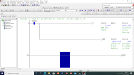
You then need to convert your HMI setting lets say 0-10 CM/H with 1 decimal point (i.e. in increments of 0.1) to 0-4000 (I assume you are using A Q68DAV module) so assuming you use a floating point register (Note: floating points use two 16 bit registers) so if your register on the HMI is D1000 then it takes up D1000 + D1001. the range is from 0.0 to 10.0 so you need to convert this to 0-4000 decimal. So you take the Value in D1000 + D1001 and multiply it by 400.0 [* D1000 E4000.0 D1002] Then convert it to an integer so [INT D10020 D1003] This will give you a conversion of 0.0 to 10.5 to 0-4000
See pic.
So to sum up you need to know the rate the pump will feed from 0-50Hz (min speed to max speed) then multiply your float value (setting on HMI) by 400 and convert it back to an integer to send to the card.
This is just a sample based on the flow rates above but the calculation is 4000 divided by the max flow at 20ma (50Hz of the pump) X your set point.
Some examples:
Max flow 10.0 CM/H then 4000 / 10.0 = 400
Max Flow 7.5 CM/H then 4000 / 7.5 = 533.333
so for 3.5 flow at a max of 10.0 CM/H then it is multiplied by 400 = 1400 sent to analogue card.
3.5 flow At a Max of 7.5 it is 3.5 * 533.333 = 1867

Scale1.png
 
Yes that is correct, First of all you need to know what the pump will deliver at the max speed (usually the speed via a VFD is 0-50HZ so lets assume that the pump will deliver 10 cubic metres an hour (or what ever your flow meter indicates). then running the pump at 50 HZ you will get 10 cm/h.
The best way to test this is run the pump via the VFD at the max 50HZ and check what flow you get.
You then need to convert your HMI setting lets say 0-10 CM/H with 1 decimal point (i.e. in increments of 0.1) to 0-4000 (I assume you are using A Q68DAV module) so assuming you use a floating point register (Note: floating points use two 16 bit registers) so if your register on the HMI is D1000 then it takes up D1000 + D1001. the range is from 0.0 to 10.0 so you need to convert this to 0-4000 decimal. So you take the Value in D1000 + D1001 and multiply it by 400.0 [* D1000 E4000.0 D1002] Then convert it to an integer so [INT D10020 D1003] This will give you a conversion of 0.0 to 10.5 to 0-4000
See pic.
So to sum up you need to know the rate the pump will feed from 0-50Hz (min speed to max speed) then multiply your float value (setting on HMI) by 400 and convert it back to an integer to send to the card.
This is just a sample based on the flow rates above but the calculation is 4000 divided by the max flow at 20ma (50Hz of the pump) X your set point.
Some examples:
Max flow 10.0 CM/H then 4000 / 10.0 = 400
Max Flow 7.5 CM/H then 4000 / 7.5 = 533.333
so for 3.5 flow at a max of 10.0 CM/H then it is multiplied by 400 = 1400 sent to analogue card.
3.5 flow At a Max of 7.5 it is 3.5 * 533.333 = 1867

Wow this is really appreciated!
Just a question: what motivates you to be so generous with sharing your knowledge? And in such detail too.
I am out of my depth but sometimes I feel a glimmer of hope that this is doable.
If it wasn't for help like this, I don't know what I'd do.
I noticed that on our PLC HMI, the motor control speed rate(of a spindle) is set on a setpoints page, where it defines the % increase or decrease speed of the motor.
Maybe I need to 'copy' this example for doing the VFD/inverter.
 
I'm now retired but like to keep my hand in, Like they say you can take the programmer out of programming but you can't take the programming out of the programmer, well a re-shaped saying lol.
Yes you could use the similar code of the existing, however, if you want it to be in cubic metres / minute instead of percent then just scale it differently.
I assume the existing code takes the set point i.e. 0-100% and scales it up to 0-4000 to send to the analogue card, There are a number of ways this might be done so you need to keep this in mind. for example, some HMI's can scale the entered value however, a quick look at GT I could not see any scaling settings so assuming this is done in the PLC.
I am assuming then that they take the 0-100% and multiply it by 40 or (4 if they use 100.0) so you will need to do the same i.e. 400. For a trial you could use the 0-100% but it does not make much sense you need to know what the pump will deliver at full speed easy checked by setting the inverter to full speed then see what the flow meter reads, this is your 100% scale so as I said earlier find the max flow, divide the raw analogue out (normally 4000) by your flow i.e. 10.0 is equal to 100 decimal.
As shown in earlier posts you can limit the upper or lower limit of the value the operator enters.
The above assumes that the Analogue card is a Q68DAN and set to normal resolution i.e. 4000 = 20ma it could be set differently so check what other channels are using.
the maths are easy take the above 10.0 CM/H is 4000 or 20ma so setting the required flow to 5.0 CM/H (4000 / 100 = 400 , 50 * 400 = 2000 ) so at a setting of 5.0 CM/H will give 2000 or 12ma (20ma - 4ma = 16ma so half 16 is 8 plus the offset 4ma = 12ma). You just need to get your head around the maths, 4ma is min 20ma is max so that is a swing of 16ma if 4ma = 0 and 20ma = 4000 then it becomes obvious that half way is 12 i.e. an offset of 4ma (offset 4ma plus the 8ma = 12ma).
see pic of the two modes I assume your card will be set to mode 1 normal resolution.
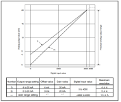
Scale2.png
 
Does anyone know the correct symbol/shape in DESIGNER3 to create triangles - something like this?

The digital display itself is not the problem.

However, I tried looking for triangular buttons on the menu down the RHS, but couldn't find anything. In the end, I had to make a freehand sketch using the polygon tool. Then I assigned 'lamp properties' to the shapes and defined a device name to each.

Returning to this old thread, because yesterday I added the digital input graphic on the GUI. It will accept whatever digit number it's meant to, and when I monitor the code, the D register has the same value.
I was hoping that the Danfoss fc102 would be expecting a value in m3/hr, but to be fair, it's not designed for that. Instead, the expected input (mA) is for controlling motor power in kW, HP or %rpm.
Is it better (and easier) to get rid of the up/down buttons and just have the digital input graphic instead?
 
Yes ythat is the normal way just make it a entry field you don't have to worry about what the units are but you need to find out what the pump will deliver from 0-full speed i.e. 4-20ma.
Then you use that as the limits you set in the HMI so for example if the pump delivers 0-50 cm3/h then you take the set-point register and convert it to the 0-4000 digital value for the 4-20 ma to the drive, however, if you do have a flow meter in the line it is better to run a PI function then you do not have to worry, just scale the digital value to the range of the flow meter for example if it was 0ma (or 4ma) to 20ma and it gave you 0-100 cm3/h then you scale it to that, then you feed your set point into the PI loop along with the process value (o-100 cm3/h) and then scale the PI output (0-100%) to 0-4000 and send that to the analogue card it will control it to what ever value you put in the set point.
The idea is you set the flow you want, it compares that with the flow meter and the PI loop modulates the 4-20 ma to the pump to keep it at the required set point. As I pointed out before, if the pump delivered 0-50 cm3/h and you wanted 25 so in theory you set the analogue output to half ( 12ma that is max - min = 16 so 16 divided by 2 (50%) = 8 + 4ma = 12ma which is half way between 4-20 ma.). but there is no guarantee that the pump will deliver 25 as the curve of the pump will not be linear, it may be close enough but is not what you would normally do.
It does depend on what sort of accuracy you need.
So in short
You take the raw value of the flowmeter and scale it to the range of the flowmeter (probably already done if existing but for the PI function it needs to be converted to a float,
Use the PI loop to compare the actual flow in real units (0-100cm3/h) with the set point you want it to achieve (note again this should be a real so takes up two registers.
The PI will give a digital value of 0-100.0 and you scale this up to the 0-4000 for the analogue out, the reason for scaling it to 0-100 is that it reacts faster you could mod the PI code to go from 0-4000 but that means changing the PI constants considerably so it reacts faster.
 
Last edited:
Wow, thanks for the detailed answer! Much appreciated.
I know that the flow meter (separate equipment and displayed on the GUI) has range 0-100m3/hr, over a range of 4-20mA. In a typical test run, the flow is approx 80m3/hr. I'll find out the full speed range of the inverter next week. Cheers.
 
Last edited:
It's not the full speed but the flow at full speed (assume 50hz) i.e. 100 cm3/h
and you only need to know it will deliver within the range you want, so assume that it will deliver it, using the PI control it will match the flow you want.
I have done many flow controls especially on CIP (cleaning in place) where set-points vary depending on the process pipe work for example 6 m3/h for spray balls to 30cm3/h for pipe work the process monitors the flow via flow meters, the PI loop compares the actual flow with the set point, this then adjusts a variable between 0-100 (%) this is then scaled to the raw values i.e. 0-4000 to drive the analogue to the VFD, no need to know what Hz value or pump speed it will ramp up/down to bring it in-line with the required set point. The trick is adjusting the PI & sample time to get it to the required level without too long ramp up, little overshoot and not hunting so you get a stable flow.
If your VFD can only use 4-20ma you till don't really need to change the analogue card parameters just add the offset of 800 will give you 4ma min on the 0-20ma setting.
 
Here is part of a program I did some years ago for a simple CIP system but only the analogues part. This is done in FDB so the code is in function blocks for the scaling & PID the same principal though, this was done for an FX PLC and GXWorks2 so the scaling is a little different.
Also this was done in integers as parameters passed to the functions where they are converted to reals as the HMI can display assumed decimal points so 1000 is displayed as 100.0
 

Similar Topics

I'm using a GT1275 HMI with GTDesigner3 and am trying to add some Alarm Logging capabilities. I've made an alarm page and have it working...
Replies
2
Views
437
Context: Mitsubishi GX Developer/GT Designer 3. At the moment on our PLC's HMI (GT Designer 3), pressing any of the SCREEN buttons will navigate...
Replies
7
Views
1,869
In GT designer 3, the rig operator wants me to display a text string on the screen when a bit goes TRUE, and make it disappear when the bit goes...
Replies
5
Views
1,885
Hello! I keep getting an error when trying to open a HMI in GT Designer 3. I go to Project->Open then select my project (GOT Type GS21**-W) and...
Replies
4
Views
2,814
In the GT designer 3 project the time looks correct, but when Iake the project "live" it's 1 hour behind. What's makes it more odd is that when...
Replies
7
Views
2,753
Back
Top Bottom