I am really trying to understand this PLC progrm stuff

What is the situation in the facility where you work? If there is someone there already familiar with the PLCs in the plant, you need to seek that person out and let him/her be your mentor.
If you have been placed in a sink or swim situation by having been assigned sole responsibility for equipment you don't understand, then your first step should be to contact your local Mitsubishi distributor and get their PLC person to come in for a visit. The distributor should be able to get you started on the correct path.
Like with some of our robots they are really unsafe they will take off when they are not supposed to and they tend to run off track and some times smash into the gate and bust threw and hang off the track half on the track and half off the track. And I would really like to add stuff to it
You're not even close to being in a position to tackle this. You should get the people who designed and installed the equipment to troubleshoot.
 
Maybe the piece you are missing is the basic understanding of what ladder logic is. The two rails (the lines that go up/down) represent positive and negative with positive being on the left and negative being on the right. The "rung" (the line that goes across) is a circuit between the positive and negative. The ladder program is run from top to bottom meaning that the top rung executes first, then the next one down and so on until you reach the bottom and then it goes back to the top. You stated that you understand NO and NC switches so let’s use them as an example. If you have one rung with a NO switch on the left (inputs on the left, outputs on the right) then on the right you have a normally open discrete output (I don’t know what Mitsubishi calls their discrete outputs but it should look like “---( )---" ). The input is tied to a switch and the output is tied to a light. When you close the input, you are closing the circuit allowing power through it which goes to the output turning the light on. When the input goes open again the circuit is open, and the light goes off. If the input was a NC, then it would be normally on until you flipped the switch then the circuit would be open, and the light would go off. If you replace the output with a timer, then when the NO input, a switch, is closed then the timer starts and when it is open the timer stops.
As others have said, watch the video and you don’t have to limit yourself to Mitsubishi video’s, the basics of ladder logic are pretty much the same across most manufactures so you might pick up info from some of the others as well.
 
P.S. I missed the piece about the Robot's, Steve is correct (please don't take the as disrespect) you are way out of your league and shouldn't be doing or at least you shouldn't be doing this without someone well versed on PLC programming helping. It might be a good learning opportunity but let's not damage anything or worse yet get someone hurt.
 
What is the situation in the facility where you work? If there is someone there already familiar with the PLCs in the plant, you need to seek that person out and let him/her be your mentor.
If you have been placed in a sink or swim situation by having been assigned sole responsibility for equipment you don't understand, then your first step should be to contact your local Mitsubishi distributor and get their PLC person to come in for a visit. The distributor should be able to get you started on the correct path.

You're not even close to being in a position to tackle this. You should get the people who designed and installed the equipment to troubleshoot.

We have never had a programmer here since 2006/2007 when they programmed the lines and that company closed down and they were based in china. The other programmer that they pay sometimes to fix our problems is also in china and even though these problems were his fault we have to pay him more money to fix them so they just put it off till it has to be done.
 
P.S. I missed the piece about the Robot's, Steve is correct (please don't take the as disrespect) you are way out of your league and shouldn't be doing or at least you shouldn't be doing this without someone well versed on PLC programming helping. It might be a good learning opportunity but let's not damage anything or worse yet get someone hurt.

I wouldn't try something like that too soon lol I am trying to understand how it all works understand it. So I can try to add stuff like counters to log how many units go down the line and like add something that can show the air pressure stuff to use with the HMI's or adjust speeds of like when the robot goes down the line and comes to the home position. I guess easy stuff well for you guys it's easy lol.
 
I wouldn't try something like that too soon lol I am trying to understand how it all works understand it. So I can try to add stuff like counters to log how many units go down the line and like add something that can show the air pressure stuff to use with the HMI's or adjust speeds of like when the robot goes down the line and comes to the home position. I guess easy stuff well for you guys it's easy lol.

Remember rule number one of this industry:

1. You touch it, you own it.

What that means, is if you make any edits to the software (assuming you will gain the required understanding first), then anything that goes wrong will be your fault (whether or not you are really to blame).

I would advise that you hire a good competent local consultant to assist you.
 
We have never had a programmer here since 2006/2007 when they programmed the lines
even though these problems were his fault
I would respectfully say that on a line that has been in place for eleven years it's a bit unfair to blame things on the program. Especially when you're citing problems like "run off the track" and "bust through the gate". Those in particular sound more like failed or out-of-position sensors.
 
Untitled.jpg

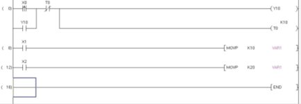
So like in this picture when X0 is activated it turns on the Y10 just under the X0 for 1 sec and then off again right where do they get the 1 sec from? If so then where does the T0 and the Y10 at the end come in to play?

And when X1 is activated it sends K10 to D0 where is D0 I don't see a D0 (which is defined with the Label "VAR1"). What label and what is VAR1

I am getting this out of the manual
 
I would respectfully say that on a line that has been in place for eleven years it's a bit unfair to blame things on the program. Especially when you're citing problems like "run off the track" and "bust through the gate". Those in particular sound more like failed or out-of-position sensors.

The sensors are fine I have replaced them and they are right were they are supposed to be the thing is lets say a unit gets stuck half on half off and the belts are running for like 10-15 seconds the robot automatically just takes off smashing the unit and jumping ****eyed on the track sitting at an angle. Or lets say a unit gets stuck on the first transfer to the push it on the robot so you hit the rest button and resets it but for some reason the robot will take off to bay 5 and the belts start turning when nothing is on it and then the transfer lifts up and pushes the unit on the floor because the robot is at bay 5 instead of at the transfer.
 
Remember rule number one of this industry:

1. You touch it, you own it.

What that means, is if you make any edits to the software (assuming you will gain the required understanding first), then anything that goes wrong will be your fault (whether or not you are really to blame).

I would advise that you hire a good competent local consultant to assist you.


That would cost me $400 out of my pocket lol was thinking about it a bit.
 
X, Y, D and M represent addresses within the PLC's memory. Var1 is an alternate way of identifying variables within the program. In your example the name "Var1" probably isn't any more helpful than the address D0 when it comes to identifying what the contents of the address D0 represents on the machine.
In the first rung of the program you show, when the input point X0 transitions from off to on the output Y0 is turned on and the timer T0 is enabled and begins to accumulate time. The NO contact associated with Y0 keeps it true, even after XO goes false. In this case the arrow pointing up denotes a transitional contact which is only true for one scan of the program logic. When the preset amount of time has passed, (defined by the K10 value above the T0 instruction which means ten 0.1 second timer increments) the NC contact associated with timer T0 makes the logic controlling Y0 and T0 false so Y0 turns off and the timer T0 resets.
 
The sensors are fine I have replaced them and they are right were they are supposed to be the thing is lets say a unit gets stuck half on half off and the belts are running for like 10-15 seconds the robot automatically just takes off smashing the unit and jumping ****eyed on the track sitting at an angle. Or lets say a unit gets stuck on the first transfer to the push it on the robot so you hit the rest button and resets it but for some reason the robot will take off to bay 5 and the belts start turning when nothing is on it and then the transfer lifts up and pushes the unit on the floor because the robot is at bay 5 instead of at the transfer.
Since I have never seen your machine, I can't begin to advise you on what might be wrong with either the way you're setting it up or the way it's programmed. In a provious post I defended the original programmer because if a machine has been running OK for eleven years and suddenly starts having problems, it's a pretty good bet that something on the machine has worn out or gotten misaligned. It's an equally good bet that the cause of the problem is not that the program has worn out or changed.
Having said that, I will freely admit that the original programmer may not have anticipated everything that could possibly go wrong and constructed the program in such a way as to minimize the consequences of those failures.
 
+1 for "you touch it, you own it", liabilities and all-Get a qualified tech to go over your equipment, Document problems beforehand so they can correct the issues.
 
Quote:
Like with some of our robots they are really unsafe they will take off when they are not supposed to and they tend to run off track and some times smash into the gate and bust threw and hang off the track half on the track and half off the track. And I would really like to add stuff to it.

Since you already think its unsafe, touching the code makes it yours and you are responsible if an injury occurs.
 
Since I have never seen your machine, I can't begin to advise you on what might be wrong with either the way you're setting it up or the way it's programmed. In a provious post I defended the original programmer because if a machine has been running OK for eleven years and suddenly starts having problems, it's a pretty good bet that something on the machine has worn out or gotten misaligned. It's an equally good bet that the cause of the problem is not that the program has worn out or changed.
Having said that, I will freely admit that the original programmer may not have anticipated everything that could possibly go wrong and constructed the program in such a way as to minimize the consequences of those failures.

Hmm they started having problems not long after they left so been happening here for years they never keep them here in the US long enough to workout all the problems. Plus few years one of the robots ran into me left a huge black and purple spot on my leg for a month because it moved when it wasn't supposed to. I told this other guy in china but he said he would have to change the hole program. If they would actually pay someone to come in here and fix all the problems these lines have it would be a good retirement fund from all the problems lol
 

Similar Topics

Local Rockwell distributor was in today. He says that the MicroLogix 1400 will likely be unavailable to purchase sometime around the end of this...
Replies
58
Views
16,585
Good Morning , I've taken on a job that is truly over my head with a engineering group. The standards of Rockwell programming is much more...
Replies
15
Views
7,003
I’ve been looking at buying a quantity of signal converters to take a type J or k thermocouple or RTD and convert it to a 4-20mA signal. In...
Replies
10
Views
2,986
Doing some consulting work using factorytalk view studio and RSLogix5000. We set up alarms for the system a while ago and they work fine, as do...
Replies
5
Views
3,615
I spent the entire day trying and failing to setup my 1783-NATR. It appeared, time and again, to be correct and happy but no matter what I did...
Replies
11
Views
5,000
Back
Top Bottom