PLC5 Bit Conversion Simplification Help (CLX Conversion)

Join Date
May 2017
Location
Regina
Posts
12
I am upgrading an existing PLC5 program to controllogix (L73 V23).

For my question I will only use the logic for my CH1 on my 1771-IFE/C.
Ch1=N26:4

N26:4 AND 1023 = D9:5

FRD D9:5 = N7:15

BTD
Source: N7:15
Source Bit: 0
Dest: N7:35
Dest Bit: 4
Length: 8

All of this seems a little excessive to me. Is there a better way to write this in controllogix?

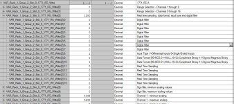
2019-03-26 Rack 0 Group 6 Slot 1 Configuration.JPG
 
So the question really is, what is the span of the input device? Just scale your CLX to match.

Just a quick glance seems like they went around their elbow to multiply by 1000. So the current reading would be 233KV. I did not go deep into it, so I may be wrong.
 
That's a bit of a head-scratcher ! A agree that somebody was trying to enforce a data limit on something, but I think the AND and he BTD are unnecessary.

The configuration for the analog module indicates that N26:4 will contain a value between 0 and 255, but the module has been set up to encode it in Binary Coded Decimal (BCD), where each 4 bits represents one digit. This was standard in PLC-2 controllers so you see PLC-5's sometimes set up to do the same.

The bitwise AND just enforces that only the first 10 bits can be used. I don't know why they did that, because all it appears to do is limit the value that can pass through to 299. Bits 09 and 10 allow a "0", "1", or "2" in the first digit, while the true bits 07 through 00 allow any value from "0" to "9".


Code:
N26:4 = 233 = 0000_0011_0011_0011
       1023 = 0000_0011_1111_1111
AND-----------------------------------------
              0000_0011_0011_0011 = 233

Then they convert from BCD to an ordinary binary Integer, so the value is still decimal 233.

Then they use a Bit Field Distribute to move the binary integer bit pattern four bits to the left, which is equivalent to multiplying by 16.

They moved eight bits, which is not more than necessary because the maximum value could only have been four bits long (255).

So the practical result is that they ended up with a value in N7:35 in ordinary two's complement binary encoding, of 233 x 16 = 3728.

If you are actually using the 1771-IFE and will be keeping it in BCD format, the simplest thing to do is use an FRD and MUL instruction in the ControlLogix.
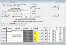

I do not use the BCD data in any way. I could probably just change it Two's Complement Binary which would just be a normal integer, correct? Then just multiply it by 16.
 
Yup ! The configuration data block would be changed by that applet in RSLogix 5, so examine all the values in it carefully.
 

Similar Topics

Hello, I am doing a PLC5 to 1756 L81 conversion. I have an issue with what looks like an indexed array bit in the PLC 5 that I am unsure of how...
Replies
1
Views
1,270
I am running a PLC5 and FactoryTalk 8.2 to control equipment at my facility. The HMI is a legacy system upgraded a couple of times which started...
Replies
12
Views
3,162
Hello everyone, My colleague and I have encountered an odd situation. We noted that, according to the historian trends, the bits in a particular...
Replies
10
Views
2,394
Anyone here using MDS Orbit radios with PLC5 serial ? If you are would you share the setup config? How does the radio deal with the DF1 address...
Replies
0
Views
1,581
I want to use PLC5 to communicate with flex IO, using RIO. Before I proceed I want to clarify my confusion about the addressing scheme, as I am...
Replies
8
Views
4,015
Back
Top Bottom