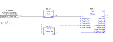
RSLogix5000_Totalizer FBD for flow transmitter

thank you soo much for your reply.

to answer ur question
1.version19
2.4-20ma flow rate,to be specific for totalizing natural gas we have fox thermal FT4A flow transmitter

please suggest how can i implement this as i have never done this and have no idea about it


I'd suggest that you consider a different instrument. I've used the Fox Thermal flow meters to totalize natural gas flow with both analog outputs and a pulse output connected to HSC modules. They worked fine -- for a while. We soon discovered that they would begin to behave erratically after several weeks of continuous operation when reading the pulse output for totalization. The only way to get them back to normal was to cycle the power to the instruments, then they'd work okay for another month or so.

We never could get a resolution to the problem via tech support. We sent multiple meters back to the factory for testing, and they were returned with no modifications and they still exhibited the same issues. These were connected to different PLCs and different power supplies and everything was installed according to specification. We finally just gave up on Fox Thermal and stopped using them altogether. Sorry to be the bearer of bad news.
 
i have to configure it using TOt function block ....so can i use the pulse output as the trigget to start TOT and start calculating the flow?

Here is a link to the unit
https://www.foxthermal.com/products/pdf/ft4a/ft4a-datasheet.pdf

It has pulse output that appears to be configurable, this should give you what you want without the need to use analogues, however it is normal to include the flow rate for real time monitoring.
you could use the output pulse to a digital input on the PLC to increment a counter, or on a one shot from the input add a value to a long integer, however at some point you may need to reset this when it goes to over flow or you could use an array of words each 0-999 and when word 0 gets to 999 add 1 to next word and reset word 0 and so on i.e. word 0 0-999 (units) word 1 0-999(thousands) Word 2 0-999 (millions), that way you can have a count into many millions and if required display this on an HMI or SCADA.
I do not have the licences installed on this pc for Rockwell but see the ladder code attached. Explanation: the input X0 is programmed as a one shot so only true for one scan, if Word D100 is less than 1000 then increment the word
compare the word with 999 and if equal to or greater then add one to D101, reset word D100, same goes for D101 & D102

So D100, D101, D102 could have a value of 999,999,999
There are many ways this can be done and could be in a function block parameterised with the input, counter or words for values etc. so you could call the FB as many times as flow meters.
I have just noticed that you state you could have 100 meters(if I read it right), the cost of 100+ analogues would be horrendous digital is the way to go.
 
attached is the program i have made....
i am using the analog input flow meter data as input and then scaling it to the flow meter instrument range and providing it as input to totalizer

this Routine will run continuously..as this is for measuring the flow rate and consumed N2 in the plant.


please suggest


Yes, THIS is the crux of the problem. As parky mentioned earlier, using the pulsed signal directly from the meter is the easiest/simplest method. You will need to dig into the documentation for that meter to determine if a pulsed output is available and how to program/wire the signal. You will also want to make sure there is adequate time for the PLC to see the pulse as it transitions between on/off so that ALL pulses are counted.

If you must use the flow rate signal, then you will need to add programming in the Logix to generate that pulse internally. Even though there meter pulse examples in this and other forums, I STRONGLY suggest you figure out on paper the steps to accomplish this BEFORE diving into programming. That step is where you learn fundamental skills that will make your job as a controls engineer/programmer MUCH less stressful forevermore!

Let's break this down: You need to create a pulse for a certain volume (1 scf, 100 scf, etc.) but you are only given a flow rate (scfm).
Step 1 is to covert into a volume. You need to know the scan time between calculations in order to do this conversion - that's why a periodic task was advised earlier.
Step 2 is to add the converted volume to an accumulated volume value, then create a pulse once the accumulated volume reaches a certain value.
Step 3 As the pulse is created, the accumulated volume needs to decrease by the certain value specified above and keep counting. The pulse bit is what goes into your totalizer input.

Hopefully this is enough to get you started. Hey, we've all had that feeling of being overwhelmed and facing impending doom. Working things out on paper first has helped me as well as countless others.

If you really are crunched for time, you may need outside help as suggested above. Whether you're in Hartford, CT or some other Hartford, it's always a good idea to develop a relationship with your local distributor.

Totalizer.PNG
 

Similar Topics

Hi! So my problem is a little funky, I had Studio 5000 v 24 and 30 installed, but forgot to install RSLogix (which I cannot go without). Is there...
Replies
2
Views
112
So I had an odd request from a customer for the above. I have written the logic and tested it all in one PLC with only using 7 outputs and 7...
Replies
15
Views
427
Hello everyone, I have an RSLogix5000 project which is running live in the factory but I need to make some changes to the logic. I want to test...
Replies
0
Views
1,120
Good Morning Everyone, I'm looking to use the GSV instruction to get I/O fault codes for my project so I know if there's a comms issue in my E/IP...
Replies
5
Views
866
The machine is running production. When trying to go online with the laptop the whole machine looses communication and faults out. Drives, HMI...
Replies
13
Views
1,932
Back
Top Bottom