Hydraulic Winch Control

shelnian

Guest
S
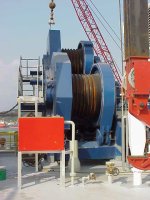
I have just been given the job to come up with a control system for a hydraulic winch assembly containing two hydraulic traction winch motors and one storage winch motor. This system will be operated on a ship at sea. Each motor is controlled by two servo valves with 0-20mA inputs and dual LVDTs and delta pressure feedback transducers for redundancy. The storage winch motor uses delta pressure control and traction winch bias to maintain 1500 + or - 500LB tension on the cable at the storage drum. The traction winches have to handle 4 modes of operation. The first mode is to not exceed 2 ft/sec reelin or out, the second is not to exceed 4 ft/sec reel in or out, the third is an automatic mode where a sensor on the end of the cable is providing feedback to the system to reel in or out to maintain a constant position, and the fourth is to maintain a constant tension on the cable on the outhaul side of the traction winch during deckside operations. At no time may the system accelleration exceed 1 ft/sec2. The system is moving a fairly heavy load up to 30kLBs. The system has blocking valves in front of each servo valve and a whole array of interlocks to ensure the system can not be operated before all required conditions are true. The traction winch motors can be operated in full or half displacement that is controlled by another set of valves. The whole system needs to be controlled from a Windows 2000 Operator interface and joystick for the none automatic modes. The system should have enough redundancy (dual control systems with automatic system control transfer) so that the package on the end of the cable can be recovered. Each control loop will need up to four PIDs to meet system operational requirements outlined above based on what the hydraulic engineer has told me. The interface between the Windows 2000 PC and the control system is a 10/100 BaseT ethernet.

My Question is, can a PLC or multi PLC system handle this level of complexity or should I be using a PC/VME to control this system? I have never used PLCs and do not have a good feel for what level of complexity they can handle. What I have read lately sounds encouraging thou.
 
Beware of those that say only, never and always.

Why not buy a hydraulic position/pressure controller that can do what you want to do? Go to google and search for "hydraulic motion control". The only problem I see is that hydraulic servo valves usually require + or - input current. Why does a servo valve require a LVDT? LVDTs are usually used by proportional valves to provide spool feedback position. In this case proportional valves usually have an electronic amplifier that converts +/- 10 volts to +/- current for the valve. The trend in the last few years is to integrate this elecronic amplifier/LVDT feed back board into the valve itself.

Other than that it is easy to find hydraulic position/pressure controllers that can:

1. Communicate using Ethernet.
2. Interface to two pressure sensors and convert the two readings to a differential force or pressure.
3. Control the acceleration and speed profiles.
4. Interfaces to analog referencs in position or velocity mode. (Joysticks)

A PLC alone may not ( probably won't ) be fast enough or have the right type of PID blocks to do what you are trying to do. A PLC CERTAINLY does not have the abilty to sample the position and pressure at equal deterministic intervals. Timed interrupts are not good enough whether the using a PLC or VME system. Controlling the transition from position to differential force/tension control can be quite tricky. In addition, wouldn't it be easier to tell the motion controller to hold position and limit pressure/tension than to try to develope, implement, and debug all these algorithms from scratch?

You can still use a PLC if you want to communicate to the motion controller or just use the PC/HMI.

The most important thing is to get a good integrator that has experience at position/pressue control. The tuition for the class of hydraulic position/pressure control at the school of hard knocks can be quite high. I know of a couple good integrators that do hydraulic position/pressure control applications and have paid tuition, graduated and know the questions and answers.
 
My apologigies, however...

Throughout the far reaches of the Universe, there is no greater Force than the Urge to Edit !!!

A couple more paragraphs would have been nice...

First, I need to say that I have worked on this type of boom system when I was in the Navy. That was before micro-chips had more than a few hundred transistors on them. Much of the control was more often by-hand than by automatic control - simply because the "automatic" systems were always failing.


shelnian said...

I have just been given the job to come up with a control system for a hydraulic winch assembly containing two hydraulic traction winch motors and one storage winch motor. This system will be operated on a ship at sea. Each motor is controlled by two servo valves with 0-20mA inputs and dual LVDTs and delta pressure feedback transducers for redundancy.

The storage winch motor uses delta pressure control and traction winch bias to maintain 1500 + or - 500LB tension on the cable at the storage drum.

The traction winches have to handle 4 modes of operation.
  • Mode-1: Velocity of Reel-In and Reel-Out NOT to exceed 2 ft/sec.
  • Mode-2: Velocity of Reel-In and Reel-Out NOT to exceed 4 ft/sec.
  • Mode-3: Automatic Mode (Position) - Automatic Reel-In and Reel-Out to Maintain constant position. Position feedback to be provided by a sensor on the end of the cable.
  • Mode-4: Automatic Mode (Traction Outhaul Tension) - Maintain a constant tension on the traction winch outhaul cable during deckside operations.

At no time may the system accelleration exceed 1 ft/sec2.

The system is moving a fairly heavy load up to 30kLBs. The system has blocking valves in front of each servo valve and a whole array of interlocks to ensure the system can not be operated before all required conditions are true.

The traction winch motors can be operated in full or half displacement that is controlled by another set of valves.

The whole system needs to be controlled from a Windows 2000 Operator interface and joystick for the NON-Automatic modes.

The system should have enough redundancy (dual control systems with automatic system control transfer) so that the package on the end of the cable can be recovered.

Each control loop will need up to four PIDs to meet system operational requirements outlined above based on what the hydraulic engineer has told me.

The interface between the Windows 2000 PC and the control system is a 10/100 BaseT ethernet.

My Question is,
Can a PLC or multi PLC system handle this level of complexity or should I be using a PC/VME to control this system?

I have never used PLCs and do not have a good feel for what level of complexity they can handle. However, what I have read lately sounds encouraging.


My response...

OPERATIONAL SPECIFICATIONS
The specifications you need to meet are well within the capabilities of most mid-level PLC's.

PROGRAM DEVELOPMENT AND PROGRAMMING
Are you looking to develop the program yourself? Or, are you planning on contracting the work out?

If you plan to develop the program yourself, then the ultimate "decider" is your ability. Do you know how to develop a program? Do you know how to program a PLC? Do you have any programming experience at all?

REDUNDANCY
You can have several PLC's running at the same time, all running the same program and watching all of the same inputs. Only one of the PLC's would actually be controlling the outputs.

The PLC's can be arranged using a "Voting" method... that is, a certain number of PLC's have to agree on what should happen. If any PLC is consistently seen to be out of agreement then that PLC would be taken Off-Line.

The PLC's could be arranged using an "Expected vs. Actual" evaluation... that is, if the response you detect does not match (within certain limits) the response you expect then that PLC would be taken Off-Line and the back-up brought On-line. The transfer would be seamless.

At some point, you are bound to run into a mechanical failure. This failure might simply result in poor response, or it might be a catastrophic failure. Having redundant hardware certainly makes the entire system more fault tolerant.

Depending on how "SMART" the program is, it might be able to determine if the failure is in the PLC or in the hardware. It might simply switch out the failing component (PLC or hardware), or, you could simply switch from one PLC/Hardware System to the other.

You can check out the failure later when you're not trying to keep 30klbs from swinging into the side of the ship.

You should also probably make provisions for a complete failure of the automatic system... that is, have a COMPLETE MANUAL SYSTEM in stand-by. However, be aware, you can take this redundancy stuff only so far.

You should be able to find a number of Windows based systems for monitoring and controlling the PLC's. That system should be able to monitor ALL of the PLC's at the same time. Use the Windows program recommended by the the particular PLC Manufacturer that you choose - don't try to use one that is not specifically recommended.

I'd like to hear what you finally decide on using. Keep us posted.


I now see that Peter has posted. He certainly makes some valid points in terms of a highly responsive system.

The question is...
What kind of response do you really need?

Any PLC will have a certain minimum scan time. The length of the program will have a direct impact on the total time. The smaller the program, the more chance the PLC has to produce a proper and timely response. And, of course, installing modules that monitor and control specific PLC-commanded effects only helps.

Remember, this particular process was handled MANUALLY, once upon a time.
 
I would love to learn PLC programming, it sounds very interesting, but I do not have the time with this project. I would appreciate any input for companies that can handle this sort of work, especially in Washington State.
I appreciate the responses, they were very helpful.
It appears that PLCs might not be fast enough to handle the PID loops and a program the size that this project will require, so a PC/VME will be required. PLCs may be able to play a roll in taking some load off the PC/VME by handling certain portions.
Does anyone think that if dedicated PLCs are assigned to the PID loops, that this system may still be able to be controlled by PLCs alone? I was thinking that if multiple PLCs can be assigned specific portions of the control (like the PID loops), with a master PLC that gathers control input data and provides commands to these other PLCs. Not knowing PLCs very well I do not know if this is possible or not advisable.
 
I have don e a similar project on a rig. Only the winches are electrical driven instead of hydraulic. We used Siemens PLC´s for controlling the winches with the help of VFD´s. The speed of the PLC wasn´t a problem for the used PID controllers in the PLC.

mvc-677s.jpg
 
Giddings & Lewis Pic900 Family of PLC's is probably the only PLC platform I would trust for this application. It definitely has the CPU speed, determinism, and very high quality hardware to perform the PID loop solving.

It programs in ladder logic, structured text, or a combination of both.

You can either use their built-in motion/process control function blocks, or write your own. We write our own. They have an ethernet module and communications function blocks for OPC and they offer an OPC driver for a PC platform so you can tie just about any commercial HMI software platform i.e. iFix, RSView, etc.

We have used this controller on some pretty exotic position/force control applications.

www.giddings.com
 
Last edited:
Trowler winch system

Hi bud,

Your application looks like a good candidate for an Allen Bradley SLC 500 PLC, a Delta Computer Systems Motion Conteroller (RMC), and a Wonderware app. on the PC.

(use pots to drive the servo valves as a back-up)

I have used Peter's "Delta Comp Sys" controllers in the past with AB SLC 500 and have been quite impressed by their capabilities.

There is a company in Washington state called "Timberline Controls". and they have experience both in this field and with these products.

Tell'em Orn from Boise ID reccomended them......

Good luck (PLC? YES)
 
I have contacted several companies (Concept Systems, Timberline Control, Duren Controls, and Systems Interface) and all are very interested in this project. I will be developing a detailed specification for these and other companies and requesting proposals. I am very curious about the different ways these companied will propose dealing with this control system. I am sure I will be back asking more questions before this is over with and I am very thankful for all the advise I have received to date.
 

Similar Topics

Hi All, I could do with some advice on a hydraulic control system. It is necessary for me to accurately position a vertical hydraulic ram with...
Replies
34
Views
1,650
Hi, I am about to start a project controlling a hydraulic ram using a Siemens S7-1200 controller. It will need to be quite steady control, by...
Replies
1
Views
703
Good Evening Everyone, I am attempting to monitor the level of hydraulic fluid in a tank. The tank is 50 gallons. For insurance purposes we need...
Replies
16
Views
4,072
Hi I have an electro hydraulic valve with coil resistance 22 ohms that takes as +/-12V DC input with 40Hz dither superimposed. The valve controls...
Replies
7
Views
2,462
I want to share a trick and see if anyone can do better! With hydraulic presses there is a point at the beginning of the actuator movement when...
Replies
10
Views
3,854
Back
Top Bottom