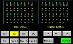
I/O Status Screens on HMI

agarb

Member
Join Date
May 2006
Location
USA
Posts
309
I hate making I/O status screens on my HMIs. As such, I usually only provide them if requested by my customer. In the past, I’ve entered these by hand and so they were tedious to make with lots of addresses and descriptions manually typed in. And then if I change or add/delete and I/O point, I have to remember to update the HMI project to match.

So I’m looking for an easier way.

So far the only thing I can come up with for MicroLogix and/or Compact/Controllogix platform with Panelview+ is to pass a parameter file to a “faceplate” that I build. I was thinking I could actually store the I/O descriptions in an array of strings and force or allow the user to enter them from the HMI. That way if an I/O point descripton changes, it is easy to update from the HMI instead of in the project.

Seems like there may already be some A/B faceplates for this but for the life of me I can’t figure out how to find them or what terms to even search for…

So how do you handle I/O status screens?
 
I created pv550 (our standard) project for all the io as detailed as possible.
the opened the new project and copied the screen or used the screen from another project. our address scheme was always the same.

at least part of the project was easy.
james
 
I created pv550 (our standard) project for all the io as detailed as possible.
the opened the new project and copied the screen or used the screen from another project. our address scheme was always the same.

at least part of the project was easy.
james


If we had a standard product, with relatively few changes from project to project, that could make sense.


But we build special machines. Often with multiple remote racks, etc. I'm trying to figure out how to streamline the process and potentially offload some of the tedious data entry away from engineering (me) and onto either my technicians or customer.
 
As a Technician . . . machine maintenance . . .
Being able to check the I/O from an HMI is priceless.

(When the machine is not working and one does not know why.)

Poet.
 
I build custom equipment as well so it's always a pain. I tell the customers if they want them, they will get the I/O addys only and not the descriptions. Only because it's inevitable that things will change a year or two down the road. 3 plant managers later they call my company complaining that the screens don't match the machine because the 2nd manager's regime changed it and the "one" guy that knew anything retired.

Doing the variable strings takes more time than the core design, and depending on how your Micrologix is set up you could risk running out of memory. Usually not likely, but still a good worst case scenario to be aware of.

The only thing to make life easier is make a dummy PV project and create some I/O screens based on possible slot configurations. Copy and paste those in. It's more work up front, but can save you some time when the project hits the floor.
 
I do the IO screens just as others have said with a PVP7s and ML1400, the long way. I can cut and paste some screens from project to project but its still a pain to go in and attach all of the tags to the Mulltistate indicators and then change the verbiage within them as well if IO changes from machine to machine.

Switching over to Compactlogixs now I would like to come up with some sort of code to make it easier as you stated, some sort of faceplate that could reference an AOI or AOI's in the controller.
 
I add these to every project I work on. It's fairly straight forward with a copy/paste of the faceplates I've designed over the years. The parameter files point to the same arrays every single time and the UDTs designed for these contain the input/output as well as a string description. As I go through my IO checks, I copy / paste the description I have in Excel to the PLC & it automatically displays to the HMI.
 
I add these to every project I work on. It's fairly straight forward with a copy/paste of the faceplates I've designed over the years. The parameter files point to the same arrays every single time and the UDTs designed for these contain the input/output as well as a string description. As I go through my IO checks, I copy / paste the description I have in Excel to the PLC & it automatically displays to the HMI.

that seems like the best way to do it, which i would like to sit down and code one day. I also read that someone did their active alarm display handling this way, which made a lot of sense when they said that they could change or add alarms within the PLC then have it display on the HMI without having to remake an .mer file to re-load into the PVP.
 
I add these to every project I work on. It's fairly straight forward with a copy/paste of the faceplates I've designed over the years. The parameter files point to the same arrays every single time and the UDTs designed for these contain the input/output as well as a string description. As I go through my IO checks, I copy / paste the description I have in Excel to the PLC & it automatically displays to the HMI.


This is what I ended up doing. I made a 32 bit faceplate and corresponding UDT. The UDT gets mapped to the module I/O bits and has an array of strings for the descriptions.


There is also a "size" field in the UDT which the HMI looks at for an animation to hide unused data points. So if it is a 4, 8, or 16 point I/O module then the extra fields get hidden automatically based on size. Or I can map 4x 8 point modules to a single 32 bit UDT.


I also made the descriptions editable but only if a privileged operator is logged in. So my technicians can edit the description fields but an untrained operator can't mess them up.


I'm using parameter files in the PV+ so I don't have to create a separate screen for each 32 point faceplate.

Very nice(y)

I had a single screen, but without description as in the image attached. Your method is definitely better. Used to do multiple screens with descriptions many years back, got tired of it due to changes in the IO along the road. An editable text field will fix the issue, great.

Do you mind post a screen shot, please.

Thank you

IO Monitor.JPG
 
If we had a standard product, with relatively few changes from project to project, that could make sense.


The end product is irrelevant for what you want to do. The real limiting factor is how much does your HMI software allows code re-use.


Without being fancy, if the HMI allows you to re-use code, all you have to do is a faceplate with 8/16/32 lights and link that to a byte/word in the PLC. This is reusable whether you're building a refinery or a packing machine.
 
This is what I ended up doing. I made a 32 bit faceplate and corresponding UDT. The UDT gets mapped to the module I/O bits and has an array of strings for the descriptions.


There is also a "size" field in the UDT which the HMI looks at for an animation to hide unused data points. So if it is a 4, 8, or 16 point I/O module then the extra fields get hidden automatically based on size. Or I can map 4x 8 point modules to a single 32 bit UDT.


I also made the descriptions editable but only if a privileged operator is logged in. So my technicians can edit the description fields but an untrained operator can't mess them up.


I'm using parameter files in the PV+ so I don't have to create a separate screen for each 32 point faceplate.

That sounds cool as hell. Would love to see a screenshot as well!
 
For Siemens S7-300/1500 plcs I do a generalised screen where you can enter the address of the Inputs/outputs you wish to monitor and the screen has 8 LED's for inputs and 8 LEDs for outputs to show their state.
 
This is what I ended up doing. I made a 32 bit faceplate and corresponding UDT. The UDT gets mapped to the module I/O bits and has an array of strings for the descriptions.

That's all well and good, unless the PLC is not running (program mode, for example), when you are trying to look at the Input points.

The way I have done it is to make 16 and 32 point templates, faceplates if you like, copy/paste them onto my status screen, and a single tag substitution on the group to point it at the I/O module data in the controller, takes but a few seconds to do, and the data will always be "live", even if the controller is in program mode...
 

Similar Topics

I've got a Powerflex 700 that doesn't like to get going in the mornings. This motor will run anywhere from 30 seconds to 5 minutes before it just...
Replies
3
Views
96
Not a PLC question but I need expert help on this. My FactoryTalk stopped communicating with the server its hosted on. I had an error stating...
Replies
0
Views
96
Hi! I am trying to run the 'SimpleSample' (https://infosys.beckhoff.com/content/1033/TF5100_TC3_NC_I/Resources/3438746891/.zip ) to understand the...
Replies
2
Views
97
Hi guys! I have 3 servos for X,Y,Z axis controlled by Kinetix 5500. In Studio 5000 there is one Predefined tag in AXIS_CIP_DRIVE called...
Replies
4
Views
152
Hi everyone i have a customer, who wants to show an alarm on the machine, if the I/O forces are enabled and set, on at ControlLogix L81E with...
Replies
3
Views
225
Back
Top Bottom