Copy Setpoint to different tag

the operator has to write to something other than directly to the output itself, then logic can use the the alarm state (1 or 0) can choose whether that operator input, or 0, goes to the output to the valve. Look at post #7.


If the operator can only write to the valve output (Local:3:O.Ch0Data), then the logic that responds to the alarm condition should not copy that output unless that output is not 0; and perhaps it should only copy that output on the rising edge of the alarm condition.
 
Last edited:
I think one piece that i'm struggling with understanding is
the operator is writing to the output of the valve and if there is a HiHi state caused by water tripping a HiHi level float then the MOV instruction over writes the operator SP to (0) to close the valve to prevent additional water from flowing in.

- The operator and the MOV instruction is writing to the same output address of the valve.

- How can i store the operator setpoint each time they make a change to the valve SP and use this tag to write to the valve after the reset button is pressed after a HiHi state?

Currently here is what i have
1. AB RSlogix 5000 1769 controller
2. MOV instruction that writes (0) to address (Local:3:O.Ch0Data) valve_output. Closes valve if the HiHi Water Level float is tripped.
3. Operator also writes to (Local:3:O.Ch0Data) valve_output via HMI software. Their able to work the valve as needed.
4. In the event there is a HiHi condition and after it has cleared. A reset button is pressed. I'd like to write back to (Local:3:O.Ch0Data) the last setpoint the operator had the valve set to.

Thanks,
I appreciate your patience

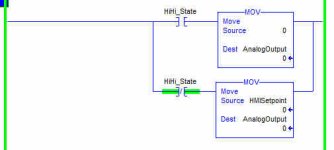
Use the HiHi state to MOV a value of zero to the output, and use NOT HiHi state to move the operator setpoint. The HMI should write the setpoint to an entirely different register in the PLC so that you don't have two things writing to the same address.

EDIT : Your basic problem is the HMI is writing to the same address that you will write zero to under HiHi conditions. This is a PLC no-no !

Personally I dislike the idea that the operator has to make changes top the setpoint, when a little bit of automation will keep that tank topped up to a good level without the operator having to make changes. The HiHi state should be a safety net, only achieved if the tank level control fails for whatever reason.

2021-04-11_205658.jpg
 
Last edited:
Here is the simple solution, but it means you have to edit the HMI application, The address HMISetpoint is what the HMI has to write to, not the physical output address.

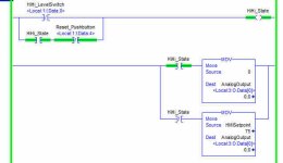
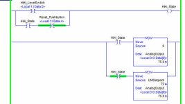
The two pictures show the output being driven when in HiHi state, and when in "normal" state. Note that I have prevented the reset button from clearing the HiHi state tag if the HiHi probe is still covered - and that it is wired "fail-safe", ON = Not covered, OFF = Covered.

2021-04-11_211849.jpg 2021-04-11_211824.jpg
 
@daba nailed it.


unless the OP cannot change the HMI application, in which case

  1. the solution is to wire the valve to another output, and use the current output as HMIsetpoint,
  2. and this is a classic forum thread where not enough information has been provided.
 
Last edited:
I can categorically say that, depending on your Logic scan time, and the update rate of the HMI writing to the output, that there will be occasions when the output goes back to the operator setpoint, only to be written back to zero by your HiHi state.

You probably haven't noticed it, the two time periods will be miles apart, but it WILL HAPPEN ! Stare at your screen long enough and you might just see it.... (bear in mind that RSLinx, which drives the comms to you online ladder display has a refresh rate of about half a second).
 
@daba nailed it.


unless the OP cannot change the HMI application, in which case

  1. the solution is to wire the valve to another output, and use the current output as HMIsetpoint,
  2. and this is a classic forum thread where not enough information has been provided.

Good one !
 
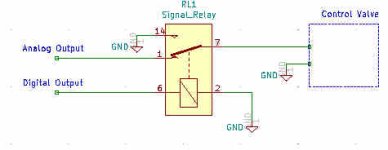
Another solution would be to add an external signal relay in the output wiring to switch the signal going to the valve from the analog output to a direct short. That will close the valve.

Don't short out the analog output !

2021-04-11_215741.jpg
 
Last edited:
Another solution would be to add an external signal relay in the output wiring to switch the signal going to the valve from the analog output to a direct short. That will close the valve.

Don't short out the analog output !

Ooh, noice!!!!
 
@Ones_Zeros: you need to tell whomever wrote the HMI code that writing direction to a PLC analog (or discrete) output is a certified Bad Idea™.
 
Thanks guys I got it figured out & tested.
@drbitboy
Just curious
How would someone change the value of an analog output
if you don’t write to the output? How would you move the valve?

FYI,
I used GEQ instruction before the MOV instruction that says
- if valve_output is >= 1
- MOV (valve_output) to (valve_SP) Most always will this be greater than 1
- in the event of a HiHi state. There is a MOV instruction writes 0 to valve_output
- since 0 less than 1. The valve_SP doesn’t go to 0
- I then use the value stored to (valve_SP) to write back to valve_output
after the reset.

Thanks everyone for helping
 
Thanks guys I got it figured out & tested.


FYI,
I used GEQ instruction before the MOV instruction that says
- if valve_output is >= 1
- MOV (valve_output) to (valve_SP) Most always will this be greater than 1
- in the event of a HiHi state. There is a MOV instruction writes 0 to valve_output
- since 0 less than 1. The valve_SP doesn’t go to 0
- I then use the value stored to (valve_SP) to write back to valve_output
after the reset.

Thanks everyone for helping

What happens if the valve is at a position X, where X>= 1, and the operator enters a 0 (or other value less than 1) via the HMI?

valve_SP will continue hold a value of X, and after a reset the that value X will be sent to valve_output, even though the last operator input was 0, will it not?

Jes' sayin'
 
3. Operator also writes to (Local:3:O.Ch0Data) valve_output via HMI software. Their able to work the valve as needed.

I would change this part. Make a new tag something like "HMI_SP_Valve_X". If the analog output is not scaled at the card, put the HMI tag into human readable engineering units (perhaps based on the flow rating of the valve). Then edit the PLC code so that the value written to the valve analog output address is either 0 or scaled from the HMI setpoint tag.

Daba is right that ideally, you would have analog tank level as an input and allow the PLC to just keep the tank where you want it, even if that target level changes during your process.
 
Originally Posted by Ones_Zeros
3. Operator also writes to (Local:3:O.Ch0Data) valve_output via HMI software. Their able to work the valve as needed.[/quote
I would change this part. ...
Yah, we have been singing those songs to OP for a few days now and they never bit. My theory is some or all of the following:

  • HMI is out of OP's control, so it will always write directly to the PLC output
    • In which case this is a case of needs-must i.e. OP can control to PLC, so use the PLC to compensate for a less than optimal HMI design
  • Operators set the valve position as part of controlling an upstream process, i.e. they do not set the valve position to control this level, and the HiHi is an emergency "someone forgot to check and empty the downstream tank and now we have to stop the upstream process" folderol.
  • OP has provided inadequate information about the process (i.e. this is a bog-standard PLCtalk thread ;))
The solution finally implemented by OP was suggested about a dozen posts back, but it does have some issues, which may or may not come up in operation (again, not exactly an atypical thread).
 
Not read most of these posts, however here is my penny worth.
HMI's do have limit controls so the values operators enter can be controlled good to stop bubba over filling a tank etc. Even in manual always put checks to shut off the process or what ever, for example on temperature control, an operator (if allowed) or engineer puts a steam valve in manual i.e. forces it to 100%, if the temperature goes beyond a safe level then the valve will shut off to stop the temperature at what is considered above what is acceptable. there are ways of reducing errors by operators & engineers. In fact, this should be part of the function design spec for operation & safety.
A couple of years ago, I arrived at work and did my usual look at the plant statuses, on one I noticed the CIP Caustic tank was 100 Deg C, I made my way to the area, the room was completely full of steam, the walls & ceiling (made of rockwool clad with aluminium & painted were peeling. An engineer on nights had put the temperature PID in manual with a setpoint of 100, forgot & went home after his shift. This system was done by others before I joined the company, so some quick mods where the temperature was checked even on manual force of the loop, A time for the maximum the system could be left in manual, an alarm banner on all scada screens that the system was in force mode, a beacon that could be seen by security, on auto log out of the engineers would turn the system back into auto.
I know you cannot cater for every situation but it pays to be dilligent.
 

Similar Topics

I have 2 7cp476 plcs. How can I copy one of them and install it somewhere else?
Replies
0
Views
69
Hello Inside a FB, I´m trying to transfer a string from a DB to a IN_OUT var that was define as a UDT. The problem is that i can´t determine the...
Replies
4
Views
124
Hi everyone I'm in a bit of a conundrum, I've been trying to get this HMI on our machine and I am unable to retrieve it. Device Delta Model...
Replies
10
Views
857
Hi I have a Melsec FX1S-20MR, which has been programmed. I would like to copy the program to a new FX1S-20MR? What are the possible ways to do...
Replies
4
Views
612
Project involves updating a ~23 year old controller (C200HX CPU64). The HMI is a windows NT machine with the gui done with Delphi 5 (Pascal)...
Replies
1
Views
1,094
Back
Top Bottom