Simple pulse generation using timers on a S7-300

sirale

Member
Join Date
Nov 2006
Location
Buenos Aires
Posts
5
Hi, I just want to use a timer to make a pulse that lasts one scan (cycle) every, say, 1 second. That is, I want for example M0.0 to be '0' for one second, then set to '1' for one scan, then set to '0' for one second again, and so on. What's the easiest way to achieve this?

Using a S7-300 PLC and LAD/FBD.

Thanks in advance.
 
This should work for you. Note if your using this as some sort of trigger for a process counter or freq counter your going to have the error of the SCAN rate (Preset + Scan Time). I would probably use the clock generator that the CPU has and apply edge logic to that flag.

Oscilator.JPG


Nick
 
Nick already mentioned using the PLC's clock memory. The accuracy of these clock bits is way better than when using timers. However, the number of blockwaves is limited, going from 0.1sec to 2sec. It goes like this:

1. Set an MB address whereto the CPU transfers the (50% duty cycle) clock bits:
ClockMemoryS.gif


The allocation of the bits is as described below:
ClockMemoryDetailS.gif


2. Use an edge detection to turn them into one scan pulses:
ClockMemoryUsageS.gif
 
Nick B said:
This should work for you. Note if your using this as some sort of trigger for a process counter or freq counter your going to have the error of the SCAN rate (Preset + Scan Time). I would probably use the clock generator that the CPU has and apply edge logic to that flag.

Oscilator.JPG


Nick

I don't have my Step 7 on this laptop, but what I do in the AB world, is compared the onboard Real Time clock's SECOND value compared to an IMAGE of the SECOND value.
When NOT EQUAL ( SECOND has changed ) EQUATE a BIT, update the IMAGE . This creates a pulse for one scan every second.

Forgive the AB version, the S7 version should be similiar:


pulse_scan_1.jpg
 
Hi, thank you so much, the tips are good.


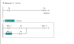
But I would like to know why, in this case, the T4 pulse does not go to "Network 10" (the idea is alternate the "M90.0" bit, each 1 second).


Please, help me, because in Rockwell PLC works well, but I did not understand why in Siemens not works.


EBoAQv379Hy4SI56i9aZyAAAAAElFTkSuQmCC


Sem título.png
 
Last edited:
My experience with S7-1200 is that feeding ~timer.Q as the EN to a timer does not create a repeating timer in Siemens. I had to feed timer.Q to a reset of the timer. It could be a branch on the same network.


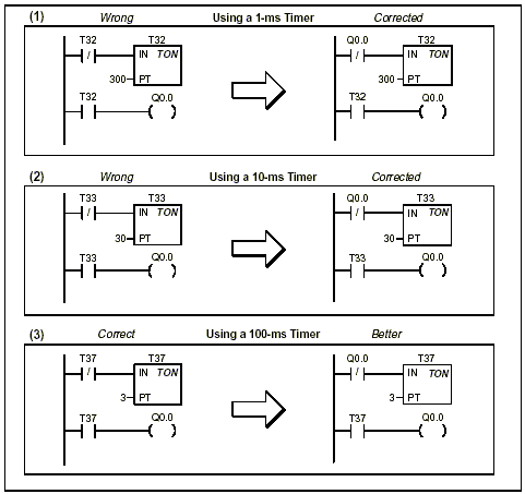
I found the info below in an ancient post on this forum.


With respect to your solution, Siemens reccommends against it. The Figure below is from their S7-2XX manual.
3d125ea14ed3a5d6.gif
 
Since you're used to Rockwell, do you know about the system timer byte in Siemens PLCs?
I don't know which processor you're using, but generally byte MB0 has pulse bits that can be used without setting up timers.

In your case, assuming it's configured correctly and running you'd use M0.5 to have a 1 second pulse instead of T4. Essentially you'd have a contact with M0.5 with M90.0 coil.
http://www.plccenter.cn/Siemens_Step7/Verwenden_von_Taktmerkern_und_Zeiten.htm
It's a tiny detail but really helpful.

Also, looking at it from afar, your code doesn't seem to do what you think it does since it's not latching and T4 only stays high for one cycle.
 
Also, looking at it from afar, your code doesn't seem to do what you think it does since it's not latching and T4 only stays high for one cycle.
I think Network 10 is correct and T4 is supposed to be high for only one cycle: it would be a flip-flop of M90.0 if T4 were the one-shot as OP expected (and as it would be in A-B). It does not need a latch because the lower branch latches (holds) M90.0's value as long as T4 is 0; M90.0 toggles its value one per scan that T4 is 1.

Replacing T4 in those three contacts there with a bit (e.g. Q0.0) and adding a rung to do this

Code:
  T4    Q0.0
--] [----( )----
after the timer should work.
 
Now I understood, thank you so much!


The T4.Q may turn on while running the project, in any moment (because timer is active). So, if T4.Q is turned on when begin the network 10, it turns off the T4 timer, turning off the bit Q (and timer variables), and it does not affect the Network 11 (it can affect if the bit T4.Q turns on exactly on the Network 11 beginning).


Thank you so much!
 
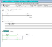
S5 timers are updated asynchronously to the program scan so the behaviour will change depending on timed interrupts etc.


For example, putting a wait between the networks and the toggle logic will appear to work.

T1.jpg
 

Similar Topics

Hello, I have a modicon background where there is a "Pulse" function that accepts an input for the deisred pulse time length. I effectively...
Replies
8
Views
2,026
Hello again..trying something on an existing poorly written program and just wanted to double check something system is an A-B MicroLogix 1200 In...
Replies
5
Views
110
Hi all, Writng a FB in ST on Beckhoff TC for a pulser which turns on and off on a cycle, is paused by turning bControlInput to FALSE, but resumes...
Replies
6
Views
247
I'm trying to build my Classic Step 7 programming skills this weekend. I get stuck on little things that are not covered in YouTube tutorials. I'm...
Replies
7
Views
314
I have a program that does a 7 second "scan" sensor calibration routine whenever a setting (setting is called assistance level or "AL" and ranges...
Replies
3
Views
211
Back
Top Bottom