speed control split phase 115VAC

snugmonster

Member
Join Date
Sep 2012
Location
missouri
Posts
2
Quite a bit of recent reading tells me that convenient speed control of a split phase 115VAC motor is either impossible or not practical. I hope that's not the case.

I have a circa 1970/80 Craftsman 1725 RPM 1/2 HP 115VAC split phase motor that I'd like to use for a fan application, mainly as a whole house exhaust fan. I have a LAU propeller on order which flows 2300 CFM at 1725 RPM at .234 HP. I could have gone with a larger prop but I don't want to suck the hummingbirds off the feeders and through the window screens.

I'd like to use a speed controller to allow drawing a decent breeze through the windows during the day and decrease the noise a bit at night, as the fan will be located in the 2nd floor near the bedrooms' open doors. I'd like to use something like the triac based KBWC-18K due to cost/availability:

http://www.kbelectronics.com/data_sheets/kbwc_data_sheet.pdf

Obviously it doesn't list split phase as a supported motor type. It seems the problem revolves around the startup winding and centrifugal switch (abbr. CS). I've performed very rudimentary non scientific testing of the CS dis/engagement. With a bare shaft no load, when I start the motor I hear a click within .5 seconds, and I assume this is the CS disengaging. When I shut the motor down it sheds RPM very rapidly, and I can clearly hear the CS reengage. It seems the RPM of the shaft at CS reengagement is less than 800 RPM. I could be wrong, this is strictly naked eye/ear observation.

So my questions for you sharp folks are:

1. If the only issue with speed controlling split phase motors is centrifugal switch dis/engagement, can this not be solved simply by always starting the motor at full power, and adjusting the minimum speed trimpot so the RPM never drops low enough during operation to reengage the CS?

2. If the issue is something else, would someone be kind enough to explain why the startup winding presents such a problem for solid state speed controllers.

3. The docs for the KB unit state one should use a prop that generates near full load on the motor (SP, PSC, universal) at full RPM for the speed controller to function properly. Is this due to some kind of current draw sensing circuit that's used to adjust the voltage?

4. I've not tested the voltage to RPM linearity of this motor and frankly I don't have the proper equipment to do so. Assuming a speed controller is even a possibility, does anyone know if these old Craftsman motors have a decent enough linearity to attempt using a voltage based speed controller?

My apologies for the length of my first post. I'm new here but not to technical forums. It's usually best to include as much detail as possible up front. In other fora I'm constantly, daily, having to ask for additional details, and the back/forth becomes an impediment to helping the person effectively, timely.
 
Quite a bit of recent reading tells me that convenient speed control of a split phase 115VAC motor is either impossible or not practical.

This subject comes up every once and a while. Most of us would consider it not practical

I have a circa 1970/80 Craftsman 1725 RPM 1/2 HP 115VAC split phase motor that I'd like to use for a fan application, mainly as a whole house exhaust fan. I have a LAU propeller on order which flows 2300 CFM at 1725 RPM at .234 HP. I could have gone with a larger prop but I don't want to suck the hummingbirds off the feeders and through the window screens.

I guessing that the motor has a frame# like 56 or 48, if so then it should be relatively simple to get a 3 phase motor and power it from a single phase input, 3 phase output VFD
http://www.automationdirect.com/adc...l)/GS1_Drive_Units_(120_-z-_230_VAC)/GS1-10P5
http://www.automationdirect.com/adc...-Phase_Motors,_56C_(0.33_-_2HP)/MTR-P50-3BD18

I'd like to use a speed controller to allow drawing a decent breeze through the windows during the day and decrease the noise a bit at night, as the fan will be located in the 2nd floor near the bedrooms' open doors. I'd like to use something like the triac based KBWC-18K due to cost/availability:

http://www.kbelectronics.com/data_sheets/kbwc_data_sheet.pdf

Obviously it doesn't list split phase as a supported motor type. It seems the problem revolves around the startup winding and centrifugal switch (abbr. CS). I've performed very rudimentary non scientific testing of the CS dis/engagement. With a bare shaft no load, when I start the motor I hear a click within .5 seconds, and I assume this is the CS disengaging. When I shut the motor down it sheds RPM very rapidly, and I can clearly hear the CS reengage. It seems the RPM of the shaft at CS reengagement is less than 800 RPM. I could be wrong, this is strictly naked eye/ear observation.

So my questions for you sharp folks are:

1. If the only issue with speed controlling split phase motors is centrifugal switch dis/engagement, can this not be solved simply by always starting the motor at full power, and adjusting the minimum speed trimpot so the RPM never drops low enough during operation to reengage the CS?

This is precisely how the Bardac brand of single phase output VFD's work.
http://www.emainc.net/downloads/optidrive.pdf . The big drawback is the price list for a .5 Hp unit is $898

2. If the issue is something else, would someone be kind enough to explain why the startup winding presents such a problem for solid state speed controllers.

There are many reasons the starting switch is a problem, the big one is that the output of the electronics do not tolerate having a switch between the controller and the motor.

In feb of 2007 a member of PLCs.net posted this response.
http://www.plctalk.net/qanda/showpost.php?p=200316&postcount=36
We have not seen him since. Here is the thread the single post came from. http://www.plctalk.net/qanda/showthread.php?p=200316#post200316


3. The docs for the KB unit state one should use a prop that generates near full load on the motor (SP, PSC, universal) at full RPM for the speed controller to function properly. Is this due to some kind of current draw sensing circuit that's used to adjust the voltage?

The reason for the need of a fan that loads the motor completely is that the controller you chose does not change the frequency of the alternating current, it chokes off the current and voltage available to the motor. The controller takes advantage of what we sometimes call fan law. In a nutshell when the horsepower is cut in half by the KB controller the motor speed would slow to 80% of full speed. This has to do with the way fan law works. Increase the speed by 20% and it requires double the horsepower.


4. I've not tested the voltage to RPM linearity of this motor and frankly I don't have the proper equipment to do so. Assuming a speed controller is even a possibility, does anyone know if these old Craftsman motors have a decent enough linearity to attempt using a voltage based speed controller?
In addition to my response above, the motor will try to go full speed and only the shaft load from the fan and lack of ability to generate horsepower will bring the speed down.

My apologies for the length of my first post. I'm new here but not to technical forums. It's usually best to include as much detail as possible up front. In other fora I'm constantly, daily, having to ask for additional details, and the back/forth becomes an impediment to helping the person effectively, timely.

Most of us would rather have the details up front, thank you.
 
Yes, what Milldrone said. Change your fan motor to some other type, or live with one speed.

Universal Motors, Series Wound Motors, Torque Motors, or Shaded Pole Motors may be able to use a variable AC voltage transformer to control the speed. You might find a good used AC single-phase universal fan motor online from a salvage company.
 
This subject comes up every once and a while. Most of us would consider it not practical

Thanks for the the quick, thorough reply and no BS up front assessment.

I guessing that the motor has a frame# like 56 or 48, if so then it should be relatively simple to get a 3 phase motor and power it from a single phase input, 3 phase output VFD
http://www.automationdirect.com/adc...l)/GS1_Drive_Units_(120_-z-_230_VAC)/GS1-10P5
http://www.automationdirect.com/adc...-Phase_Motors,_56C_(0.33_-_2HP)/MTR-P50-3BD18

That's a bit pricey for what will essentially be a window fan on steroids. If I end up replacing the motor to get speed control for less noise, I've previously located a number of much less expensive motors and controls.

This is precisely how the Bardac brand of single phase output VFD's work.
http://www.emainc.net/downloads/optidrive.pdf . The big drawback is the price list for a .5 Hp unit is $898

Just a bit. ;)

There are many reasons the starting switch is a problem, the big one is that the output of the electronics do not tolerate having a switch between the controller and the motor.

You seem to be suggesting the centrifugal switch lies between the electronics and the main windings. AIUI, the starter windings and main windings of a split phase motor are energized simultaneously, the starter windings providing higher torque to get the shaft up to speed quicker. When the shaft hits a certain RPM the centrifugal clutch breaks the circuit to the starter windings only. Thus, the only thing the electronics see differently than with an SP/PSC motor is simply a drop in current flow a fraction of a second after startup.

I'm not surprised nobody has designed their fan speed controller to allow for this. I'm guessing it has more to do with economics and applications than technical obstacles. Split phase motors are designed for quick spin up with high shaft loading. Applications where this characteristic is needed rarely, if ever, need continuously variable speed control, but are usually constant speed applications.

In feb of 2007 a member of PLCs.net posted this response.
http://www.plctalk.net/qanda/showpost.php?p=200316&postcount=36
We have not seen him since. Here is the thread the single post came from. http://www.plctalk.net/qanda/showthread.php?p=200316#post200316

That thread, and his post, are what lead me to join and ask my question. I'd hoped maybe there had been new developments in the interim 5+ years.


The reason for the need of a fan that loads the motor completely is that the controller you chose does not change the frequency of the alternating current, it chokes off the current and voltage available to the motor. The controller takes advantage of what we sometimes call fan law. In a nutshell when the horsepower is cut in half by the KB controller the motor speed would slow to 80% of full speed. This has to do with the way fan law works. Increase the speed by 20% and it requires double the horsepower.

I should have realized this. The phenomon is similar to wave drag, http://en.wikipedia.org/wiki/Wave_drag In the case of fan blades air resistance increases at a much faster rate than shaft speed.


In addition to my response above, the motor will try to go full speed and only the shaft load from the fan and lack of ability to generate horsepower will bring the speed down.

When sizing props for this motor, I stayed away from any that required more than .5 HP at 1725 RPM, assuming that they'd drag the motor down to an RPM lower than the design speed of 1725 and burn it up. If I installed a prop that required .75 HP at 1725 RPM, at what RPM would it actually turn with a .5 HP 1725 RPM motor? Would this overheat and damage the motor? Or would it simply spin happily at the lower RPM? In other words, could I use an oversized prop to both decrease noise due to lower RPM and increase airflow to boot?

Most of us would rather have the details up front, thank you.

I didn't get them all in the first post, but I tried to get the meat of it. Thanks Vaughn.
 
You seem to be suggesting the centrifugal switch lies between the electronics and the main windings. AIUI, the starter windings and main windings of a split phase motor are energized simultaneously, the starter windings providing higher torque to get the shaft up to speed quicker. When the shaft hits a certain RPM the centrifugal clutch breaks the circuit to the starter windings only. Thus, the only thing the electronics see differently than with an SP/PSC motor is simply a drop in current flow a fraction of a second after startup.

I have an experiment for you if you believe your statement above is true. Take the motor apart and place a piece of paper between the contacts of the start switch. Try to start the motor, it will not run. What the start winding does is apply a retarded or advanced magnetic field (in relation to the main winding) to the motor to give it a direction to run.

The arc that happens when the contacts open are very detrimental to the electronics. However permanent split capacitor motors do not have these contacts. Shaded pole motors also can be controlled. The problem with shaded pole motors is Hp, rarely are they available above 1/15 Hp


If I installed a prop that required .75 HP at 1725 RPM, at what RPM would it actually turn with a .5 HP 1725 RPM motor?

My best seat of the pants guess is around 1640 RPM.

Would this overheat and damage the motor?

Yes

In other words, could I use an oversized prop to both decrease noise due to lower RPM and increase airflow to boot?

Not the way you are going about it.
 
Hi All!!

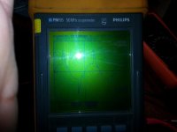
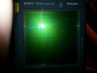
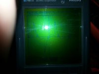
Revamping this tread because I have similar problem. I'm trying to control the speed of smallish permanent split/cap motor (< 1 Amp) via very simple R/C phase shifting diac triggering BT136 triac circuit. I tested it with resistive load and it is behaving as expected. However when I attach the motor I get voltage waveforms measured ACROSS THE MOTOR as in files attached.

154107 - Full speed setting
154053 - Half speed setting
154133 - Very low speed setting, motor stalls

To make matters worse, this motor is coupled with 1:50 (approx) gearbox which is integral and can't be taken apart to run motor just by itself.

What I observe is that motor pretty much doesn't change speed. Just gets weaker, its easier to stall when grabbed by hand.

What I'm after really is conformation from someone knowledgeable that these waveforms are right / wrong and if this solution is not really how to control the speed for what ever reason.

Many thanks in advance!!!

20160313_154053.jpg 20160313_154107.jpg 20160313_154133.jpg
 
I am not an Elec Eng, but I do notice that the period of all your waveforms are 5ms. You appear to be only 'chopping' the voltage available to the motor. You need to vary the frequency.

Have a look at charging up some caps and creating a modified sine wave using a 555 circuit
 
I am not an Elec Eng, but I do notice that the period of all your waveforms are 5ms. You appear to be only 'chopping' the voltage available to the motor. You need to vary the frequency.

Have a look at charging up some caps and creating a modified sine wave using a 555 circuit

Thanks for the help!

You are right. It is only a chopped voltage with triac. It's a very simple circuit. I used this previously on universal motors and heaters with no problems. Permanent split motor is obviously different beast. What you are talking about is basically building a small inverter.

How are these motors with modified sinewave? Well square wave in reality.


Thanks again!
 
I don't know, hopefully someone else will reply. And yes, a small VFD. I assume you are just exercising your curiosity with this project?
 
I don't know, hopefully someone else will reply. And yes, a small VFD. I assume you are just exercising your curiosity with this project?

Yeah I'm hoping that someone will give their opinion on it as well.

I was exercising simplicity of the circuit and hoping that it will work like I wanted it too and not like it work now :)
 
In lieu of an experienced response, if I was trying this with a couple of components, and to be quick and dirty, I would create a full wave rectifier, the output of which feeds 2 SCR's. The SCRs would be triggered alternately by a 555 circuit. One SCR is wired to provide the positive cycle, the other the negative. This will give you a square wave of varying period. If you get crafty with your 555 you will also be to trim the width of the pulses, thereby controlling RMS voltage close to 240V.
But with the lagging currents the motor will have, this setup may not even work at all!!!
 
ROAMER_AUS,

I'm not an engineer. But I think your approach is wrong. I can only give you layman's terms for what you need your output to be.

You will need a "carrier" signal somewhere around 1 khz to 10 khz. This carrier will need to be pulse width modulated (PWM) to "simulate" a sine wave. In your case somewhere around 0-50 Hz.

Perhaps this website will explain it better.
http://myelectrical.com/notes/entryid/152/variable-frequency-drive
 
Thanks for the help both!

Uhmmm looks like split phase motor doesn't like chopping triac circuit since everyone is steering in inverter pwm direction. Which in this case gets a bit too complicated.
I was hoping to keep the simple circuit that I used before and maybe add some filtering to avoid those weird looking waveforms.
 
ROAMER_AUS ,
Bear in mind that the capacitor is there to provide a * FIXED * time offset to give a rotating magnetic field . Only small changes in speed are possible plus square wave voltages are likely to give spikes which shorten the capacitor life . For this application , you may be better off with a DC motor - a lot easier to design your own speed control circuitry .
Paul

Thanks for the advice. I'm starting to think the same. Although wouldn't it be better to use brushed unviersal motor? Or is this what you had in mind?

Thanks again!!!
 

Similar Topics

Hi all, I'm having trouble solving a problem I've been working on for several months, and thought you might like a stab at it. The machine runs...
Replies
22
Views
944
Does anyone have any experience with working on piezoelectric motor control? I want to use off the shelf components to hopefully change the...
Replies
5
Views
737
I have two drives that control two seperate pumps that need to control pressure for plant cleaning. The company wants one pump to be running and...
Replies
4
Views
688
Hi, I've bought this PLC + HMI from Aliexpress, the one on the right that uses SSRs. and want to connect a 24V/0.2A DC fan to the output. My...
Replies
32
Views
7,087
Hey everyone! I'm searching for an example demonstrating how to program in Studio 5000 speed control of a PowerFlex 525 drive via Ethernet. While...
Replies
1
Views
653
Back
Top Bottom