Help with Cam profile.

Elcan

Lifetime Supporting Member
Join Date
Apr 2008
Location
NC
Posts
935
Hi All,
I'm translating an AB motion program (RSLogix 5000) to another PLC brand, and I need to reproduce a Cam profile.

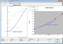
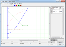
Please see attached "Cam Editor AB.PNG". This picture shows the Allen Bradley Cam Editor window. You will see the Master and Slave values (just 3 rows). The corresponding chart is the blue line.
For the new PLC, I need to provide all the Master points, from 0 to 25 (or 24). I could just look at the points in the Cam editor and manually write the values, but I would like to have a more efficient solution for future situations like this, and also learn about how to create cam profiles.

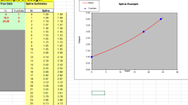
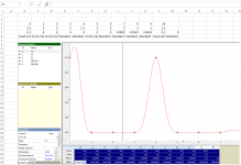
I downloaded an Excel spreadsheet with a spline formula, and got the interpolated values and chart as shown in attached picture "Excel Spline.PNG".

The problem is, at the beginning of the chart, I am not getting a smooth acceleration like with the AB Cam Editor. You can see that the Excel chart between 0 and 18.20 is almost a line, but in Cam Editor is more like a curve.

I noticed that the interpolation between the second and third point in Cam Editor (0 and 18.20) is defined as "Linear", but I don't see how to mimic that in Excel, I don't know how to trick formula by adding additional points to have a smoother start of the movement. I don't know if this is the reason for the different chart, though.

I'll appreciate you feedback. Be aware that I'm still in the process of learning about motion, so bear with me!

Thank you!
Cam Editor AB.PNG Excel Spline.PNG
 
It looks like the Excel example does not use the same end constraints for generating the spline as the AB cam profile does. Look at the attached image. From simple inspection you can see that these curves start very differently. If you look at the Cam Editor lower right is states that start and ens slope will be zero. To use Excel, you have to use a function that will follow those constraints.

Does the spline function that you are using have any options for specifying end conditions?

spline.png
 
Does the spline function that you are using have any options for specifying end conditions?
I see what are your saying.
No, I don't think the formula I'm using considers any end conditions.
Having said this, what would be the recommended tool(s) to use in cases like this?
 
Elcan, a normal cubic spline allows one to specify the velocity or acceleration at the end points but not both. Normal splines do not allow you to specify linear segments ( Rockwell ) or fixed or constant segments ( Delta )., Excel simply implements normal cubic splines. We, Delta Computer Systems, realized long ago that this was not suitable for motion control so we did some mathmagic that allows the specifying of both velocities and accelerations at the end points. Other motion control companies to the same to varying degrees.

The Rockwell png above is a simple example but there mathemagic behind it that isn't shown and that cannot be duplicated with a normal spline routine.

The short answer is that I doubt you can copy just X and Y values from a motion control cam table and paste it into excel and get all the information that is really contained in the cam table.

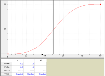
In the cam below there are just two points for a move from 0 to 1 in 1 second. The velocity and acceleration at the end points are 0 and 0.
Only the data for the two points is visible a lot of extra math is done behind the scene so that both the velocity and acceleration are 0 at the end points.
Try making a cam table like this so the velocity and acceleration are 0 at the end points using just two points.

Simple Spline.PNG
 
You can download this program. It it called RMCTools
http://deltamotion.com/files/rmctoolsinstall64.exe
You can cut and paste from RMCTools to Excel and back. I am not sure it will help getting the information to the "other" controller.
Thank you very much, Peter!
I just used your tool and it works in order to reproduce the curve, but I din't find how to define, for example, 10 interpolating X points, get the corresponding Y values, and to be able to export the obtained table to Excel.
 
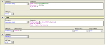
If you have a controller, you can write a program to use the CRV_INTERP_Y function to get a bunch of points into an array and then copy them to excel.

I'm guessing you don't have an RMC so the brute force method would be to turn on the hairline on the curve plot (right click and show hairline). Then in the properties window, make sure the hairline tab is selected and keep moving the hairline to see the points at that X value.

See the attache for an example.

If you only have to do this once it's not bad. If you have to do it a bunch of times you're better off using a controller that can make the cams for you.

Hairline.png
 
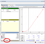
You select the data in the spread sheet part of the curve tool then..

copy it to Excel.
The data in Excel can be copied to make new curves in RMCTools because we made it possible to do so. I don't think that all four rows will copy to another controller. Only the first two row will probably copy to another controller.

Basically there is no compatibility or standardization for the bottom two rows although the velocity row should be an obvious 3rd row. The fourth row is definitely not standard. Rockwell uses slightly different terminology for how the interpolation is done between points from what we use.

Norm showed how to use the hairline and explained that there are functions to read the y value or position (CRV_INTERP_Y), velocity (CRV_INTERP_V) and acceleration (CRV_INTERP_A) at each point. I also have a user program CRV_INTERP_X so that if you know Y or the position you can compute the time or master position.

It may be easier to user our controller. The first 3 rows are numbers. The fourth row is text. There are only 3 text options. This is easy to generate using Excel or the VBA. It is also possible to simply download the curves by passing Excel. In the saw mill industry the curves are generated and downloaded on-the-fly. No two curves are the same. This is called curve or shape sawing.

Select and paste.PNG
 
Last edited:
copy it to Excel.
I understand, but you can copy the points that you (manually) entered. There's no way to ask the tool to generate a certain number of interpolating values, and then copying them elsewhere.

Thank you for your feedback anyway!
 
Like I said, you would have to write a program and use the interpret function to get points from the curve that the program generates.

I did that for the points you seem to have.

CAM.PNG
 

Attachments

  • Elcan_CAM.xls
    39 KB · Views: 25
There's no way to ask the tool to generate a certain number of interpolating values, and then copying them elsewhere.
Yes there is. In fact very few cams are entered by hand. Maybe only 0.01% if that many that are create by hand. Most are computer generated and downloaded.

We have user programs that use structure text to do the math. There is a CURVE_ADD command that will create a cam using data in a table. The problem is that you need one of our motion controllers to do this.

Another option for you is to write a VBA program in Excel to generate the points to do what you want. You could probably do this in VB.net or C#.net too. Look at the code in Numerical Recipes in C. The problem is learning the mathemagic part that isn't in the book that allows selecting velocity and type for each segment.

If you are very ambitious, you may be able to add cam table code to Archie's Advanced HMI so you can directly download to the other PLC or motion controller.

Just so you can see how we ( our customers actually ) use cam tables.
http://deltamotion.com/peter/Videos/JAN-04 VSS_0001.mp4
Each log is scanned then an optimizer determine the best way to chip these small logs. The optimizer generates 6 cam profiles per log. There are about 80 points per cam profile, one every 3 inches or sometimes 2 inches. There are 6 actuators that follow a curve that is geared to the feed chain. No two logs are the same so 6 new curves are generated for each log. The 6 cam tables are downloaded while the previous log is being chipped. Since there are 100s of similar machines out there doing the same thing I think very few splines, curves or cams are generated by hand relative to the computer generated spines.

We still have no clue what you are really trying to do. What is the application? For instance many people use cam tables for flying shears etc but there are better ways to accomplish flying shears without cam tables.

Sometimes simply doing a 3rd order interpolation between 4 points on-the-fly is enough. Few could tell the difference between on-the-fly interpolation and a true cubic spline.

I see Norm has written a small example using our structured text. Norm generates points but they need to be in a format for the CURVE_ADD advanced points so the extra data that determines how to interpolate can be included.
 
Last edited:
We still have no clue what you are really trying to do. What is the application? For instance many people use cam tables for flying shears etc but there are better ways to accomplish flying shears without cam tables.
I had the reference X and Y points and the chart in an Allen Bradley program. What I was trying to do was to generate the interpolating points to be used in a another brand of "PLC" (Trio controller) that I had thought it didn't have the tool to generate the points itself. I found out that their software had a tool that lets you enter your reference points, along with speed and acceleration at the boundaries, and it will generate the interpolating point to be used by their PLC program.

Thank you very much for your help!
 

Similar Topics

Hi all, Now I am working with Sicam P50 multi function meters. It have 2 sets of Analogue outputs. I want to know how we can check its working or...
Replies
0
Views
1,514
Hello, I have an Alfa quatro bottle labeller which is being a bit grumpy at the mo. There is a blade on drum that rotates and this in...
Replies
1
Views
3,357
Could anyone be of assistance in testing or reviewing some YTERM code for the ECAM function on a SMC-4040 Yaskawa controller? I am experiencing a...
Replies
0
Views
1,624
This may be a shot in the dark, but am needing help with an old 5TI-3201 TCAM (Timer Counter Access Module). I have no manual and am trying to...
Replies
3
Views
1,991
I'm fairly new to Rockwell software, I've had some basic training in the past but nothing too advanced. My company and I use Reliable products for...
Replies
9
Views
188
Back
Top Bottom