Need Help/Advice about DC Output Module

roar06

Member
Join Date
Feb 2018
Location
Calgary
Posts
5
Hello everyone. this is my first time posting on this forums so please forgive me if the format of my question is unclear.

background information: i am working on a project which is to automate a greenhouse using PLC 5/40L.

The first task is to program the DC Output Module to produce a constant 24V DC. The output of this module will be use to power our LED grow lights, the end goal is to have a timer for which it will power the lights for 8 hrs and turn off, and repeat the next day.

The DC module has been inserted and configured according to its data sheet. Now, i have no experience in PLC and have no idea how to begin, so i need advice on how approach programming this to accomplish our task. The software we have is RSLogix 5.

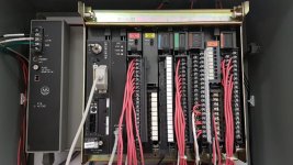
I will attach pictures of the setup so far.

Related Info:
Cat. no. 1771-OBD Output Module
Chassis Type: 1771-A2B (8Slots) - PLC - 5/40L

Thank you so much for taking the time to read this post.
Have an awesome day
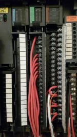
DC Output Module Setup.jpg Overall Setup.jpg
 
First off I hope you understand that that module is only callable of 2 amps (or 48 watts) per output with a total module output of 8 amps (or 192 watts). Any larger load than that you going to need some kind of contactor/power relay on the output.

If your using 2 slot addressing then the output address will be O:002/00 thru O:002/17, remember PLC-5 IO is always octal addressing.
If your using 1 slot addressing then the output address will be O:004/00 thru O:004/17.
 
Last edited:
Power the lights from your 24VDC supply, through a relay that is controlled from your output card. Not directly from the output card.
 
Power the lights from your 24VDC supply, through a relay that is controlled from your output card. Not directly from the output card.

Thank you for the reply,

How would i begin to program this in RSLogix 5?

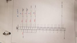
I have an 1771 - OW 16/B Relay Contact Output Module

I will attach a picture of the wiring diagram for this module.

15217611894391474346879.jpg
 
Last edited:
Ok- you said DC output module which is different. Relay outputs are better but I would still use separate relays to keep from wearing out your expensive card.

You need to look into using timers. TON, RTO. There are multiple ways to do this. Check the manual or help file in RSLogix 5 for examples of how to use timers.
 
Power the lights from your 24VDC supply, through a relay that is controlled from your output card. Not directly from the output card.

Ok- you said DC output module which is different. Relay outputs are better but I would still use separate relays to keep from wearing out your expensive card.

You need to look into using timers. TON, RTO. There are multiple ways to do this. Check the manual or help file in RSLogix 5 for examples of how to use timers.

Sorry for the confusion. I will do what you suggested, thanks.
 
Why not?

These PLC 5s must be unkillable if people are still doing projects with them!

It's a greenhouse, I have a PLC5/20C, four slot chassis, two SIM cards and internal power all for under $500 invested that I use in a trainer. Reliable and easy to find parts, are still widely used. That's why I still support one in my trainer, people are asking for hands-on training even with 5 series processors.

Regards,
Sydney
 

Similar Topics

I will be building a panel and I want to make sure that I am staying to code. I know that I need to worry about SCCR Ratings, and Panel FLA...
Replies
4
Views
2,903
I have a customer who has a Galileo app that is about 5 years old. We bought the Galileo software from Moeller to make some small changes. I don’t...
Replies
2
Views
2,650
Have an 800HP Robicon CSI drive (ID CSI 456980.00 fyi).. and when the drive runs at/above 44Hz I get over voltage faults. I've looked at the clamp...
Replies
7
Views
3,602
Here is a project I need some help on: I have a motorcoach I'm converting into a home (you can view pics at www.WonderlandBus.com). I want to...
Replies
3
Views
5,537
Back
Top Bottom