PID Tank Level Question

JoseM

Member
Join Date
Jul 2011
Location
Texas
Posts
381
I'm wondering if you guys can help me decide the best way to go about controlling the level on a tank. I want to use a Pneumatic actuator and butterfly valve. The actuator has a 4-20 ma control signal to regulate the opening of the valve. The tank has a level sensor that will be used as a feedback to control the level.

I want to know if for this kind of application, I need to use a dedicated PID controller or can I used the PID function on a 1756-L62 CLX5562 controller.

Ask questions please if I have not being clear enough on what I'm trying to do.
 
How large a tank?
What is the tank diameter?
What is the valve flow rate?
Is the valve regulating inflow or outflow?

I would suspect that the AB PID instruction would be able to handle this as well as most stand alone process controllers.

Keith
 
absolutely you can use the PLC. I'm doing something very similar using the PID instructions with an L16ER. Using a pressure sensor to sense the level in the tank, and an I/P converter and a diaphragm-actuator valve to close the flow. As long as the butterfly valve can be controlled well, you should be able to make it work.
There's also PIDE, but you have to have more than ladder logic to use it.
 
Yes if you really need to keep the level at an exact level. If not you can just define hi and low points and start/stop the fill.
But yes pid is easy enough to use in plc. Something like that should tune real easy. Probably won't even need any dirivitive factor.
 
Thank you for the quick reply. Here are some of the information about the process.

Tank Diameter: 8 feet
Flow Rate: 137.5 GPM
Tank Height: 13'-6"
Nominal Capacity: 5K Gallons
Inflow Regulation

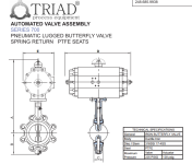
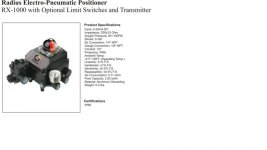
Pneumatic Valve.PNG Positioner.jpg
 
Is the exact level important? If not, it might be easier to just write your own short P only routine, where the valve opens to 100% at say a 40% tank level, and closes fully at a 90% tank level. Anything in between sets how far open the valve is. So the calculation for valve position is:

Valve Position(%) = ((90% - (Tank Level %)) * (100/40)

Otherwise yes, the PID block will be a piece of cake.
 
Last edited:
I'm trying to minimize shockwaves through the PVC line by slowly opening and closing the valve to maintain tank level.
 
If you really aren't too concerned with a specific level but just want to "taper" the valve open and closed, I would go with rupej's solution. Since this is an integrating process you will settle at the setpoint level with proportional only control if there is no outflow. This is easy enough to do that I would implement this as discrete instructions as opposed to using a PID instruction, as rupej indicated. This kills two birds with one stone; gentle open/close and rough level control.

Keith
 
The more I think about rupej answer the more a lean going in that direction. Thank you all of you guys for the advice.
 
There are two levels at which to approach this problem

As an engineer/designer or PLC programmer just trying to get the job done.
Since this is a PLC forum I try not to geek out too much but since a link to an engineering article was posted I will put my geek hat on.

Z-N shouldn't be used for tuning tank levels. Not even modified Z-N. Z-N was developed in the dark ages, BC, before computers. Now the math for tank level control is perfectly understood. There is no need for trial and error.

In-flow and out-flow tank level control is two different problems. How can one Z-N method work for both? Controlling the in-flow can be a more difficult problem than controlling the outflow. Why?

JoseM has done a pretty good job of describing his tank system. What he hasn't told us is linear or non-linear the valve is or how does the fluid flow out. If there is an orifice at the bottom of the tank but the there is no back pressure then the out-flow will be proportional to the square root of the level in the tank. If the fluid outflows based on a varying demand then it is important to know that. What screws up many people is that the time constant isn't always constant in a tank level control system. What if the surface area of the tank changes as a function of level like a horizontal cylinder. Z-N won't help there.

However, the simple proportional band should work well enough.

I would really like to teach a college class on tank level control because it can be simple and understood intuitively but if one wants to get into the details there is a lot to learn that can be applied to so many other systems.
 
I want to revive this thread. I need to make a correction on the specifications I mention earlier,

(Inflow) Butterfly Valve: 302 GPM
(Outflow) Pump: 275 GPM

4-20 mA = 0 - 90 Degrees (Valve)

I want to add a RIO analog module (DeviceNet) to drive the positioner on the valve assembly to control the level. Can you guys help me with the function needed to drive the positioner through the RIO and the computational formula that is going to determine the error correction on the level.
 
Couple of clarification points:

1 - "RIO" is actually a network. Universal Remote I/O Typically associated w/PLC5 controllers and SLC controllers. But can be used on CLX controllers but usually only for PLC5/SLC migrations.

2 - You mentioned DeviceNet, which is another network. Both networks can control remotely located IO modules/racks. You may want to provide more detail. Safe to say you mean to refer to DeviceNet?

The thread has provided some good advice, controlling through a remote analog module using DeviceNet doesn't change the control scheme. It becomes more of a DeviceNet configuration to ensure the "raw" signal to the analog channel is properly communicated over DeviceNet. Which leads to using RSNetworks for DeviceNet, and mapping your analog module and updating the DeviceNet scanner card.

As for the 4-20mA to 0-90 degrees (I typically use 0 - 100% open), this is just a scaling problem where y=mx+b is your friend. Plenty of threads on this.
 
Since now we are giving out specifications:

1) what is the level tolerance you want to hold
2) do you have access to the pump flow information
3) does the source upstream of the butterfly valve have a constant pressure
4) do you have flow versus percent open data on the butterfly valve

Whether you need to answer 2, 3 or 4 kind of depends on your answer to #1.

Keith
 

Similar Topics

Hey guys Thanks in advance for the help. Equipment - Boiler, with 2 position level switch (full and low) Variable supply valve...
Replies
19
Views
10,572
Hello All, I am currently working on Controling the water level in a tank using a PID instruction in RSlogix 5000 via VFD. I have set my...
Replies
4
Views
3,205
Hi everyone, Im having some questions regarding how to tune the PID for this application. It is a jacketed tank, lets say 1000 liters, and its...
Replies
17
Views
6,428
Dear all, I have quite an experience in programming PLCs but it is the first time I get to Implement a process control. This is not a thread...
Replies
5
Views
5,529
Hai welcome to automation world recently i am working on MICROLOGIX 1100 i did the operation for PID block. that is one tank is there and one...
Replies
1
Views
4,100
Back
Top Bottom