Give one solution

Velpandian P

Member
Join Date
Aug 2019
Location
Tamilnadu
Posts
4
Hi,*
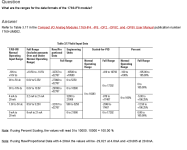
We are working with AB-CompactLogix L32E controller including Compact I/O 1769-IF8 analog input module. We have been configure 1769-IF8 module as engineering units (Min 4000 to Max 20000).

At the analog input side we have connected Non-Loop powered 4-20mA Amplifier as per 1769-IF8 wiring drawing (Iout+ to Iin+ and Iout- to V/I in-). The amplifier successfully generate the 4-20mA signal without oscillation at the output terminal. But the controller shows only 3200 (engineering unit) value with no change.**

We don't know what's the problem*is. Also we had double check our input wiring connection and module configuration there is nothing wrong. Apart from*that please give us solution to eradicate this problem and*give any suggestion.
 
Thanks for your response

Hi ken,

yeah, it's right but that is full range engineering units for 3.2mA to 21mA. we want only 4 to 20mA signal that's the reason for choosing 4000 to 20000.

And one more think, I want to inform you. We had already get the output from plc properly by our old amplifier pcb board, which contains only normal components. but now we have go to new pcb board. here we replaced some normal components into SMD components.

After that, we are struggle to get the output from plc.
 
A value of 3200 is suggesting open loop.

Have you a mA meter you can put in series with the circuit connected the PLC and check that you have mA there.

Also is the instrument active or passive with the mA signal?
 
Rob,

I understood the word "Instrument" is 4-20mA Amplifier as you put in the comment. it is a active device, which means it require external power to provide the output.

Already we measured the mA signal by using multi-meter at the output terminal of the amplifier. Even we had checked in the terminal point (Iin 0+ & V/Iin 0-) of the 1769-IF8 module and it shows clearly, the linear variation of 4-20mA. but the plc doesn't read the mA signal.
 
Your description of the wiring suggests a differential signal. If it is single ended then the wiring should be + to In+ and - to V/I in - and ANLG COM.
 
It may also help if you let us know what specific device you are connecting to the IF8 module, of if you can post the documentation for it.
 

Similar Topics

Hello everyone, I'm working on a project that involves controlling an array of nozzles within a CNC environment, where the nozzles travel along a...
Replies
5
Views
176
Our plant has a network repeater station located in a field with two ProSoft RLX2-IHG network radios for connecting our plant network to a well...
Replies
9
Views
2,402
Hello. This is one for the Mitsubishi experts. I need to measure the time for a remote device's to return process data sent from the i-QR...
Replies
17
Views
2,118
Hi all, I have a customer who wishes to to display some of the information from their refrigeration plant (CompactLogix PLC on Ethernet/IP) on...
Replies
9
Views
1,509
Hi Guys, I developed HMI with Resolution of 1920 x 1080 in FactoryTalk View studio SE; and also use same resolution for Client Runtime PC yet...
Replies
0
Views
553
Back
Top Bottom