Safety Relays....

milmat1

Member
Join Date
Aug 2005
Location
North Carolina
Posts
209
I have been out of the business for some time due to a disability. Now that I am back to work (as a trial) and trying to get up to speed I am having a very hard time.

My present problem is understanding safety relay's. These things for some reason have me so confused I don't know which way to turn...LOL

I need a safety relay to monitor two estops and also will be connected in series through several SEW MOVAXIS drives. ( built in safety contacts).

The more I read and study the more confused I get. And figuring out how to draw/wire this is really presenting a problem.

Anyone have an explanation of these beast or some secrets of safety relays...
 
Hi Matt,

No secrets i'm afraid, but there are a few basics that need to be followed!

It really comes down to (safely) removing forms of energy from your equipment without presenting further risk to operators.

Can't give exact details of the procedures over there, but over here, in principle, we start with some form of Risk Assessment. This will determine the key principles of your safety circuit design (level of category design, circuit monitoring etc.) then from this you can decide on types of (say) safety relay type, single/dual channel etc. Most of the main safety device manufacturers have very good example designs showing typical applications for e-stop, guarding, motor rotation etc.

Your two e-stops, for example, could be wired in series and monitored by a single safety relay, or you could wire each e-stop to a dedicated relay and monitor each circuit separately. This will give a higher category of protection, but may not be necessary depending on the result of your initial risk assessment.

The above is very generic - but hopefully points you in a useful direction. Be prepared to comply with all relevant safety directives and regulatory requirements when undertaking safety circuit design...it can get very involved!!

Welcome back btw!

Rob
 
Rob,
Thank you for the information. I have began reading the information on the AB website and several others as well.
I am having trouble with how to interact my safety relay with the built in relay in the drives. They have a dedicated safe relay and coil for same. In each drive, Gets confusing for sure....

Thank You
 
If you are asking about an MSR210 style safety relay it works in the following manner.
There are two (2) redundant e-stops circuits that follow the same Path, They both go to the same safety relay and when the circuit is made both paths have to be made with in given time or the relay will not set. And when the E-stop is pushed both paths must be broken for the relay to be reset when the circuit is closed again. This whey if one of the physical contacts becomes fused somehow then the relay will since this and not reset itself. It is just an added safety to a redundant safety circuit.
 
To add to Rob's comment it is not just to shutdown safely but to do it reliably. Modern safety standards deal with how likely the system is to shutdown safely.

There are two main measures depending on standard. PL or Performance Level and SIL (Safety Integrity Level). PL is measure a,b,c,d,e; PLa the least safe, PLe the most safe. SIL is measured 1 to 4, 4 being the safest (4 typically not used in machinery safety, think Chernobyl).

I think in some cases the confusion is caused by calling them safety relays (although it is the standard term). They are more than a simple relay. They in fact are as much monitoring and logic unit as they are relay.

A typical safety relay has one or more inputs. Inputs are most often redundant (depends on safety requirements), meaning you should have a single e-stop switch with two outputs. This way the relay can see if either contact is not working properly and if so shut down safely.

The logic in the safety relay prevents you from reseting if it detects a problem. Most safety relays also use pulse testing on the inputs that will detect shorts and opens.

The output is also monitored to ensure that when commanded to open the contacts indeed open. Some relays have dual outputs to control two external relays. Some are even redundant internally, so that even if an output contact fails internally the relay still opens.

Safety relays are almost a safety system unto themselves.

Now, for your specific case. The safety relay in not actually controlling your load, it's output contacts can be thought of interposing relays between the controls and final actuating element in this case the drive because it was designed to be used in a safety application (note that it does NOT actually remove power from the drive, it disables the pulse train to the output, which prevents any torque being developed). I believe this drive is also capable of a safe stop 1, i.e. decelerates under power then disables itself, so that you can stop high inertial loads faster than just letting them freewheel to a stop if you simply removed power.

There are two safety inputs in your drive. Depending on the results of the hazard analysis you will need to wire one to achieve PLd or both to achieve SIL3.

With each safety input there is also feedback. This way the safety relay can monitor that the drive complied with the request to shut down.

Safety has come a long way since we just wired an e-stop switch to a master control relay.
 
Last edited:
Hi Milmat,
Allen Bradley do a booklet named safebook 4 which can be downloaded free from http://www.emea.rockwellautomation.com/oem/ru/safety/free_safety_guide.aspx
Please be aware that this booklet is intended for European standard EN 13849-1 but the concepts of the safety terms will be the same. It will give you a good insight into the requirements of the risk assessment which is the initial step to designing the safety circuit.
Also Pilz have a manual that shows working examples of using their safety devices to incorporate estops/ door switches, etc. It can be downloaded at
www.galco.com/techdoc/pilz/pnoz_x_app.pdf
Hopefully these documents will give you a good insight into the requirements of safety circuits and how to design/ wire them.

Regards,
Donnacha
 
Welcome back Matt,

Matt said:
...I need a safety relay to monitor two estops and also will be connected in series through several SEW MOVAXIS drives. ( built in safety contacts)...

...I have began reading the information on the AB website and several others as well.
I am having trouble with how to interact my safety relay with the built in relay in the drives. They have a dedicated safe relay and coil for same...

Have you, or others, done any kind of a Risk Analysis for this safety design?

It sounds like they are MXA81's? These have one Safe Torque Off (STO) safety relay, incorporating a coil and one normally closed feedback contact. Having only one built in safety relay they will do up to Category 3 PL d.

I don't know what your controlling with these servos, but they support group disconnection, so you can possibly do this using one safety relay, but, first you need to decide the stop category required.

If an Emergency Stop is activated, is it safe to do an uncontrolled stop, stop category 0, of all the servos?
If a safe stop, stop category 1, is required on one or more of the servos, then you cannot use group disconnection, and will require a safety relay incorporating a delay off for each stop category 1 servo.

If you are using safe stop category 1, upon emergency stop activation, the safety relay delays triggering the STO. Before this delay times out, you must drive the servo to a stop using a brake ramp specified via setpoints. Because the brake deceleration is not monitored by the safety function, you have to be very careful that if the servo has not fully decelerated when the STO is triggered, there may be a potential risk to persons. Your Risk Analysis should take this into consideration.

If you only require stop category 0, then group disconnection will make this relatively simple to setup.

Depending on how many servos you want to add to the safety relay, each servo STO relay coil consumes up to 950mW, so make sure the safety relay's contacts can handle this.

I have used an Allen Bradley MSR121RT(Cat no. 440R-J23102) SIL 3, Cat. 4, PL e safety relay before for a similar job to yours.

Whether PILZ, AB, or what ever, use a dual channel safety relay, with at least two instantaneous safety contacts(stop category 0). It must have manual monitored reset. Both emergency stops should have dual contacts to wire the safety relays dual channels through.

It's better to break both the positive and the negative going to the STO relays through the safety relay. This method also prevents having to wire the STO relay supply and feedback in separate cables.

So wire the 24VDC supply for the servos STO safety relay positive and negative through the instantaneous safety relay contacts and in to X7:1(24VDC+) and 2(24VDC-) on the first servo. You can then loop this to each subsequent servo STO safety relay. You must use the normally closed feedback contact from each servo(X7:3,X7:4), wired in series, with the manual monitored reset circuit. Do not use automatic reset on the safety relay.

If the safety relay has an non safety auxiliary contact, you can also wire a safety relay status input to a PLC.

I've attached a rough drawing of how you would connect one emergency stop and one SEW MOVIAXIS STO safety relay to an MSR121RT.

For two emergency stops, just wire both channels in series through both stops.
Channel 1 = S11,S12
Channel 2 = S21,S22

For more than one servo, wire the STO coils, X7:1 and X7:2, all in parallel and the feedback contacts, X7:3 and X7:4, all in series with the reset circuit S33 and S34.

Any questions, ask away.

G.
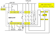
MSR121RT - SEW MOVIAXIS.PNG
 
I see a very strict narrow focus on safety equipment, safety relays, and safety procedueres. Don't forget to step back and take a look at the total system to see if some things (put in for safety purposes) actually work with the other equipment to create unsafe conditions. PLC programs should also be written to be safe, even if there are other legally required safety systems that are supposed to take care of all safety issues. Here is an example:
Nozumi, Japan’s first planetary mission, was launched on July 4, 1998, on a mission to Mars. During one of the trajectory burns the anti-back-flow valve did not fully open. The anti-back-flow valve was added as part of the bipropellant propulsion system to prevent flow of the oxidizer through the pressurization lines that could result in mixing of fuel and oxidizer and inadvertent ignition or uncontrolled venting. One such scenario was theorized as causing the loss of Mars Observer in 1993. Because the valve did not fully open the rocket could not provide sufficient thrust and spacecraft could not enter an orbit around Mars. Therefore, a control for a known failure led to mission loss.

Lessons Learned: Controls must not be considered in isolation. For example, while a sprinkler system may help control a fire hazard, it could introduce a new hazard related to electrical shock or short circuiting of other critical systems. Or, as in this example, controls could introduce complexity to the system, resulting in new and unforeseen failure modes. Therefore, the analysis should include the potential for new hazards introduced by the hazard controls.

Harland, D.M., and Lorenz, R.D., Space System Failures: Disaster and Rescues of Satellites, Rockets, and Space Probes, Praxis Publishing, 2005, pp. 188-189.
 
Geospark, That is basically what I'm doing. Thank You. I will try to post a drawing here shortly that shows the recommended setup from SEW. It demands a safety relay with time delay though. I had assumed this would be to allow the safe stopping of the axis.
BTW Doesn't the use of a master control relay somewhat defeat the purpose of the safety relay.
 
Geospark,. that's basically what I'm doing. I'll try to post the drawing from SEW showing several axis' connected to a safety relay.
Though it request a relay with a time delay. I had thought this delay was to allow for the orderly shutdown and stopping of the axis.
 
Those are feedback from the drives to the safety relay.

If you look at Geospark's drawing you will see that if the safety relay does not properly de-energize, you will not be able to reset the safety relay. This prevents you from restarting if there is a fault in the drive's safety circuit.
 
OK I see what your saying. However in the drawing there are two coils/relays in the drive. Coils paralleled and NC contacts series.
I guess I really need more info about the drives functioning. They are very different than what I am used to......
 
Refering to the document you attached above. On page 37 each drive has one contact and one coil. So, all the coils are wired in parallel and the feedback contacts in series. This configuration can be used in up to PLd and SIL 2 applications. This means they are relatively safe, but they are not the safest application.​

On page 39, each drive has two coils and two feedback contacts. Again all the coils are in parallel and the contacts in series.​

However note what happens when if one of the relays in a drive were to fail closed. In the configuration on page 37 the drive in question would not be disabled by the safety relay and you have to rely on the enable signal from the PLC to shut it down. If the reason you hit e-stop was that the PLC went crazy--no bueno.​

In the page 39 configuration, if one of the relays were to fail closed, the drive would still be disabled by the second redundant relay in the drive. This redundant configuration allows use in PLe and SIL 3 applications. It safer because the probability of both relays failing at the same time is much less.​

The feedback contacts are checked to see if all the relays de-energize properly. The contacts are positively-guided (sometimes called force-guided) which will close only if all the main contacts are open. So, if one did fail it can be detected and repaired before the second one fails and you lose your ability to stop the drive.​
 
Last edited:

Similar Topics

Hey guys, the scenario is: I have already completed the drawing package for my system utilizing an A-B 440R-N23126 (Minotaur) safety relay. SoS...
Replies
0
Views
126
This is not exactly PLC question. I have application, where SIL 2 pressure sensors need to be used. I was not able to find any SIL 2 pressure...
Replies
6
Views
1,774
Hi all, has anyone ever had any issues with premature failure, etc. when using contactor relays on pulse monitored safety outputs? We are...
Replies
0
Views
762
I have panel which controls a batch pasteurizer. The panel has an E-Stop and a safety relay (Schneider XPSAC5121) which cuts power from all DOs of...
Replies
11
Views
4,571
Hello everyone, I have some problems with safety relays and AS-i. I need to draw project for my final exam, but I don't know how to use/wire them...
Replies
3
Views
1,633
Back
Top Bottom