![]() ![]() ![]() ![]() ![]() ![]() |
||
![]() |
||
![]() ![]() ![]() ![]() This board is for PLC Related Q&A ONLY. Please DON'T use it for advertising, etc. |
||
![]() |
![]() |
#1 |
Member
![]() ![]() Join Date: Oct 2017
Location: UK
Posts: 6
|
how best to create these pulse signals for a sim program s7-1200
Long time reader first time poster.
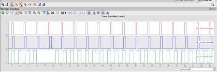
I have the following pulse signals as attached generated by an OEM machine. I am aiming to recreate the waveforms in order to test another program I have developed as an add on. The top 2 wave forms (product holders) are constant on the machine. The bottom wave(represents a product present in the holder) is more likely to be high or low. I have created some logic with a myriad of timers and set bits but it is not robust IMO or constant. It would probably do for testing tbh, but this has me thinking surely there is a better way. I have looked at enabling the system and memory bytes as a clock but it is constant, can it be manipulated? I'm looking some inspiration and direction to reach a half decent solution. |
![]() |
![]() |
#2 |
Lifetime Supporting Member
![]() ![]() Join Date: Nov 2006
Location: UK
Posts: 6,228
|
What logic are you using to create the green trace?
Post your traces from the plc for the top two showing what is not constant/robust
__________________
S7-300 to 1500 conversions done - email to s7conversions@hotmail.com Last edited by L D[AR2,P#0.0]; April 8th, 2021 at 04:45 AM. |
![]() |
![]() |
#3 |
Member
|
From your description it does appear to be a bit shift system, but I do not understand the waveforms the way I interpret it is that the top ones represent a product in a location (to me this is bit shift register pulses) the bottom one would be if a part is present in the shift register. so in reality the waveforms do not give the relevant information.
For example a rotating table with say 12 stations has an encoder or some form of pulse counter so as the table rotates if a part is present and loaded at the first station then as the table rotates it shifts a true along the bit shift register. the 12 stations could represent 12 bits so one bit per station if on rotation a bit in the shift register is true then you know it has a part. it could also have a hundred bits and every say 10 bits is a station. I think we need a bit more information. If my idea is not what is actually happening then I think you need to explain the process a little more. |
![]() |
![]() |
#4 |
Member
![]() ![]() Join Date: Nov 2016
Location: Fields of corn
Posts: 1,815
|
I don't think anyone will be able to create this without an understanding of what the system really is and situations you want to simulate for logic testing.
|
![]() |
![]() |
#5 |
Lifetime Supporting Member
|
Welcome to the conversation!
It looks like the vertical grid lines are at 0.200 intervals.
Scheduled tasks (A-B terminology, sorry) would be one way to cut down on the inter-scan variability, but could a task be run at 1ms intervals if that was the accuracy requirement? Pulse duration is another issue; I think monitoring the accumulated time, .ET, of a TON would be the best way to handle this. ... and don't call me Shirley (couldn't resist ![]() Last edited by drbitboy; April 8th, 2021 at 08:30 AM. |
![]() |
![]() |
#6 |
Member
![]() ![]() Join Date: Feb 2005
Location: Manchester
Posts: 1,580
|
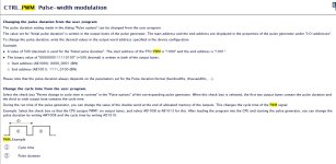
A question to the Siemens experts. Couldn't this be achieved using the Pulse Width Modulation function? I am used to Pulse Train Output but haven't used the CTRL_PWM (Pulse width modulation) function, and so am not familiar with the settings available in the associated DB. If the ONs and OFFs were of equal length I would say use PTO, but this looks very much like a PWM signal. PWM works outside the PLC scan rate, so is not limited by speed of timers.
You would need a DC/DC/DC type PLC, or you can add DC outputs but they only seem to be NPN rather than PNP, and so would need conversion.
__________________
Knowledge is power, share the knowledge. Last edited by BryanG; April 8th, 2021 at 09:24 AM. |
![]() |
![]() |
#7 |
Member
![]() ![]() Join Date: Feb 2005
Location: Manchester
Posts: 1,580
|
Answering my own question, yes the PWM function should do what you want. I didn't know if you could change the width of the pulse and the cycle time of the pulse, but you can. This is from the TIA Portal online help. And you don't need to make changes in the function DB, just use the Hardware IO Address.
__________________
Knowledge is power, share the knowledge. |
![]() |
![]() |
#8 | |
Member
|
Quote:
I don't think a PLC is the right tool for this job. I would try a Raspberry PI or similar. I know that if I used my relatively expensive motion controller it would be done by now but you guys will waste much more time than the cost of the motion controller trying to make the PLC work.
__________________
"Living is easy with eyes closed, misunderstanding all you see...." Strawberry Fields Forever, John Lennon |
|
![]() |
![]() |
#9 | ||||||||
Member
![]() ![]() Join Date: Oct 2017
Location: UK
Posts: 6
|
Quote:
Quote:
Quote:
Quote:
Quote:
Quote:
Quote:
Quote:
![]() the machine can be seen here, https://www.youtube.com/watch?v=ISo5S_YEwDo the trolley wheels (carriers) trigger the blue and black pulse the green pulse is triggered by the product. I just want to emphasize this is a post to create a better test program, the actual process involving SHL bytes in a word to keep track I am ok with. |
||||||||
![]() |
![]() |
#10 | |
Member
![]() ![]() Join Date: Oct 2017
Location: UK
Posts: 6
|
Quote:
![]() |
|
![]() |
![]() |
#11 | |
Lifetime Supporting Member
|
Quote:
Awesome. I went back and watched it at one-quarter speed. With the lack of accuracy required I don't think this will be beyond what the S7-1200 can do. I would think sub-5ms 3-sigma accuracy is possible, which sounds like it's good enough. there could be a good fraction of that much noise in the chain sensors. My approach would be
It may be worth caching the .ET value at the start of every scan, rather than reading from the TON block, where it may change throughout the scan. Last edited by drbitboy; April 8th, 2021 at 01:28 PM. |
|
![]() |
![]() |
#12 |
Member
![]() ![]() Join Date: Feb 2005
Location: Manchester
Posts: 1,580
|
Using the equipment that you have. Set up a PTO Pulse train output at say 10 times the frequency of the fastest signal. Connect a piece of wire from the high speed output to a high speed counter input. Use the High Speed Counter to count the incoming pulses. Set the High Speed Counter interrupts at counts that give the ONs and OFFs that you need. It gets over any timing issues between pulse streams, uses the kit that you have and a programming language that you are used to. If you use the :P on the ONs and OFFs commands you write directly to the Outputs avoiding any delays in the process image that is used in the main cycle.
__________________
Knowledge is power, share the knowledge. |
![]() |
![]() |
#13 |
Lifetime Supporting Member
![]() ![]() Join Date: Nov 2006
Location: UK
Posts: 6,228
|
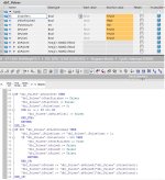
Set up three arrays containing 500 bools. Set the bools in the array to the values you want for the waveforms. In a timed interrupt OB (10ms), output the value from each array according to an index, then increment the index. Finish when the index gets to 500
Resultant trace (using plcsim)
__________________
S7-300 to 1500 conversions done - email to s7conversions@hotmail.com Last edited by L D[AR2,P#0.0]; April 8th, 2021 at 06:14 PM. |
![]() |
![]() |
#14 |
Lifetime Supporting Member
![]() ![]() Join Date: Nov 2006
Location: UK
Posts: 6,228
|
Example code:
__________________
S7-300 to 1500 conversions done - email to s7conversions@hotmail.com |
![]() |
![]() |
#15 | |
Member
![]() ![]() Join Date: Oct 2017
Location: UK
Posts: 6
|
Quote:
I had a stab at this before work today, blue and black pulses are working well, green needs some more time spent to work out correctly. Thanks for your input I will post the FBD when I have it sitting pretty. |
|
![]() |
![]() |
Bookmarks |
Currently Active Users Viewing This Thread: 1 (0 members and 1 guests) | |
Thread Tools | |
Display Modes | |
|
|
![]() |
||||
Thread | Thread Starter | Forum | Replies | Last Post |
CPU BASED PROGRAM LOCKING in S7 | arc | LIVE PLC Questions And Answers | 3 | May 28th, 2006 06:30 PM |
S7 Program execution | RMA | LIVE PLC Questions And Answers | 4 | May 19th, 2005 07:11 AM |
Simulator, Simulation, Shadow Code | Terry Woods | LIVE PLC Questions And Answers | 1 | January 2nd, 2005 02:40 PM |
S7 224 - Storing String variables in a program | ltrail | LIVE PLC Questions And Answers | 4 | November 30th, 2004 07:18 PM |
S7 CPU Parameterisation problems after loading program | RMA | LIVE PLC Questions And Answers | 12 | October 7th, 2004 10:12 AM |