Stuck Technology student!!

Ivy K

Member
Join Date
Jan 2003
Posts
3
HELP!!!
My PLC knowledge is pathetically simple and I am stuck on a undoubtably simple problem. Ladder logic is troubling me and my simple problem is this; program a push button switch (PB1) to illuminate a light (IL1) that will, when pressed again, turn the light off. For some reason I cannot wrap my mind around this and I would be greatful for any insight into why I am so troubled (I'm too ashamed to ask the Prof.).

Ivy K
 
I will go one further, I will show you how to alternate between 2 outputs...to just use 1 output remove the 2nd output.
Code:
| 
|Input 1                                                  Internal 1 
|--] [-------------------------------------------------------( )-- 
| 
| 
| 
|Internal 1 Output1                                      Out 1 
|--] [--------]/[-----------------------------------------( )-- 
|                      | 
|Out 1      Internal 1 | 
|--] [--------]/[------| 

If you ever want to alternate between 2 outputs just add another line. 
Out 1                                                     Out 2 
|--]/[------------------------------------------------------( )----

Input 1 is naturally the N.O. momentary or start pushbutton
Internal 1 is the plc internal bits..For AB that would be B3..GE %M000 etc etc]
Out 1 is Output 1
Out 2 is Output 2
If you decide to alternate between 2 outputs I will leave it up to you to figure out how to turn off both outputs when needed.
 
Last edited:
Here is the wiring diagram

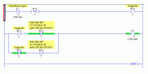
Just write ladder like this. No Timers.. No Counters.. Just simple..
Your prof will surely appreciate..

ons.gif
 
You have to think about how the PLC scans...top to bottom and left to right.
This code works for me.

The ons(oneshot) only allows the pushbutton to be seen for one scan when it is on.
The pushbutton must go false and then true again for the program to be seen again.
When the pushbutton is pressed the first time this happens.
Since b3/1 is off b3/2 turns on.
Since b3/1 is off b3/3 does not turn on.
After you release the pushbutton and then push it again this happens.
b3/1 is true so b3/2 does not turn on.
b3/1 is true so b3/3 turns on and unlatches b3/1.
B3/1 could be a real world output o:1/0 or b3/1 could be used to turn on the real world output.

i:0/0 b3/0 b3/1 b3/2
--] [---------[ons]------|-]/[-----( )---
|
| b3/1 b3/3
|-] [-----( )---

With b3/2 true b3/1 turns on and latches.
b3/2 b3/1
--] [------------------------------(L)--


When b3/3 is true it unlatches b3/1
b3/3 b3/1
--] [------------------------------(U)--

Hope this helps
Johnp
 
Ivy
Sorry that that code got messed up when I sent it I will try to get it straight and send again. The wording at least appears ok.
Johnp
 
johnp, a tip, when you do a ladder use brackets [] with the word code inside it at the start of the ladder and /code in brackets [] at the end of the ladder.
Code:
 i:0/0         b3/0       b3/1      b3/2 
|--] [---------[ons]------|/[------( )---
| 
| b3/1    b3/3 
|-] [-----( )--- 
|
| With b3/2 true b3/1 turns on and latches. 
|  b3/2                            b3/1 
|--] [------------------------------(L)-- 
|
|  When b3/3 is true it unlatches b3/1 
|  b3/3                            b3/1 
|--] [------------------------------(U)--
 
Last edited:
Rs,
Have you tested this code? Won't your code produce a very fast flashing light? At least it does with my plc. Just curious.
Tim
 
Rsdoran
Thanks

I put the ]b3/1[----(b3/3) in a branch after the ons. Can you explain that for me.

Ivyk, look at Rsdoran's drawing.
 
tim
I havn't tried RS's code but he diagrams well.
Try the code I sent just move the ]xicb3/0[----(b3/3)---
to the right of the ons and make it a branch under the
]xiob3/1[---(b3/2)
Johnp
 
That was johnp's code I just missed a fact

Code:
 i:0/0         b3/0       b3/1      b3/2 
|--] [---------[ons]----+-|/[------( )---
|                       | 
|                       | b3/1    b3/3 
|                       |-] [------( )--- 
|
| With b3/2 true b3/1 turns on and latches. 
|  b3/2                            b3/1 
|--] [------------------------------(L)-- 
|
|  When b3/3 is true it unlatches b3/1 
|  b3/3                            b3/1 
|--] [------------------------------(U)--

I didnt look at the code, I was attempting to help display it. Looks ok to me now that its displayed properly.

I stand by my orginal reply, its simple and can be carried over to most platforms or converted to alternate (flip flop) between 2 outputs. I dont use Set/Reset or Latch/Unlatch very often if at all.
 
Ivy
You can also try this
Use two up counters to count the pulse from PB1.
Counter 1 with preset =1 The second with prset =2
Use NO contact from Counter1 to on your lamp (IL1)
Use NO contact from Counter 2 to reset both counter.
It may be more complicated than the guy's offer but it works
Sorry for not implementing this in Ladder If some one could do it for me this time it will be great.
I am still new to this site.But i found a post in the site regarding this issue i'm studying now.Again Sorry for any inconvienient
 
Rs,
I may have misunderstood your code. Is your internal 1 relay a one shot relay? I don't know AB or GE bits so I just had to ask.
Thanks in advance,
Tim
 
I dont know why it would create a flashing light, the input will make the internal bit go true which in turn if output 1 is not true will make output 1 true which will make output auxillary 1 true and because internal 1 is now not true (scan time plays a part in this) the output 1 should latch. Once latched if you push input 1 again it should unlatch.

This is in my collection of default type code so I know it should work but I will test it again tomorrow.

No one shot is involved but may work better if that is an available instruction. Internal bit means a memory bit or internal relay bit..in AB it would be b3, with GE Fanuc it would be %M0001 or %Mxxxx, for automationdirect it would be Cx (x being a number and C being a control relay that is software..ie internal) or maybe R in some cases, in Siemens Step 7 they are M type example M2.2.

Those are the 4 main programs I deal with, siemens also offers a "toggle" instruction that will allow you to use 1 input to turn on/off one output or toggle between 2 outputs.
 
Last edited:

Similar Topics

Hi, I am using M221 reading from 3 different sensors (modbus rs485) sharing same bus (daisy chain). I am currently using READ_VAR (in total...
Replies
0
Views
84
I'm using one TON (called SystemTimer) throughout a program that I change the .PRE given different conditions. I'm porting an IDEC ladder over to...
Replies
8
Views
315
We have a keg check weigher that that lost a fight to a forklift. The scale was previously a Systec IT3000, which was the only PROFIBUS slave...
Replies
5
Views
672
really strange issue. The panelview(2711p-T10C22D9P) will try to load an application and get stuck on "Starting Alarms". If I reboot the...
Replies
4
Views
1,444
Have an issue with a couple of KTP700F HMI's that gets stuck on the startup in the Windows screen and not loading the HMI project. THis is not the...
Replies
3
Views
1,393
Back
Top Bottom