Micro800 PID question

One thing I want to add is that, since your model specified the PV (temperature) in percent, you are pre-scaling that value going into the Micro800 PID block as percent. This, of course, requires your set point to be pre-scaled using the same relation as the PV. You do not want to feed the PV as percent and set point as engineering units. And if you change them both to engineering units (e.g., degrees C), the gain will need to be adjusted accordingly.

Yes, sure. PV & SP are prescaled to %% from Fahrenheit and CV scaled to an appropriate range of VFDs reference speed (also in %%).
I'm using a 60-95 F range for scale output temperature to PV.
 
N.B. there is a typo in Post #8: ".Ti and .FC" in the third paragrpaph should read ".Td and .FC." It is restated correctly in later posts, so that should not be source of @Peter's confusion. Everything else is, AFAICT, correct.

TL;DR


The rest of this post is all about returning @Peter generous trolling in kind; so feel free to ignore it as there is absolutely nothing new in it. I know, because I did the work to reverse-engineer how the CCW/Micro800 PID instruction works, and I made my best effort to ensure that everybody, but one, who bothers to read my posts to this point should be in the same state.

Yes, but you did it with the derivative gain active too. I can see the proportional gain acts as expected because after the derivative term decays there is only the proportional term.

And you did the derivative term with the filter on. That clutters things up.

Wrong again. actually I did it before that and recorded the result in my first post cf. post #5.

[Ti] ... I don't see it. You didn't tell us if it works as expected so how are we to know?

Wrong again, cf. post #5.

Or maybe, if @Peter Nachtwey doesn't see something it does not exist? Do we all cease to exist every time he blinks? If a Peter blinks in a forest, ...?

NO! In post #8 you have FC labeled as the derivative gain. If it is a filter time constant ...

which it is not
; wrong again: in any instance of the PID_GAINS structure/object in the CCW/Micro800 episode of The Twilight Zone,the .FC member expresses the quantity usually referred to as "derivative gain." I have stated that I don't know how many times; is @Peter blinking every time he skims over it?

Which is it?

Wrong again. "Which is it" implies I have been saying FC is more than one thing, which I have not.

FC should be set so there is no derivative filter.

Wrong again. First of all and for the umpteenth time, .FC is not the bloody filter time constant. cf. every post of mine post #6.

Second of all, if either or both of .Td and .FC is/are 0, then there is no derivative action cf. post #5 and post #6 and post #8.

The FC should be in the denominator,

Wrong again. That would be true if the FC was indeed a time constant, but it is not.

I am not confusing the issue.

Wrong again. By continuing to treat FC as a time constant, which it is not even though that has been stated many times, although, because you have held to your presuppositions like an I don't know what, and refused every vain plea to challenge them for so long, I suspect you are the only one confused.

What is the equation that the Micro800 uses? ... When a low pass filter is added to the derivative term it is
CV=Kc*(1+s/Ti+Td*s/(Tf*s+1))
s is the Laplace operator...

Code:
              /      s           FC  *  s      \
             / 1  +  --  + -------------------  \
CV = Kc  *  (        Ti     / Td      \          )
             \             (  --  * s  )  +  1  /
              \             \ FC      /        /
Prove me wrong.

Caveats

Kc, Ti, Td and FC being the four members of the CCW/Micro800 PID_GAINS object structure, in that order, assuming Ti, Td and FC are positive.

N.B. I did intend, and the data support, putting FC in the numerator, as well as the denominator of the third term, as well as Td in the numerator of the denominator of the third time. I an that makes no sense semantically, but remember that derivative gains and time constants, by any other name, would smell as sweet.

N.B. This only answers the query "What is the equation that the Micro800 uses?" posed above; any relationship of those PID_GAINS members' to the canonical meanings of identical names in control theory is apparently accidental at best.
 
I don't want to get into the middle of the lovely debate here, but I would like to attempt to follow along. Your attachment seems to be missing from post 16.


Thx!


Set CCW up like the image in post #8, with SP=PV=0, push the [Play] button on the trend, tweak the tuning parameters as desired, then type in -100000 for the output_of_model/pv_to controller quantity, and hit enter. the CV will jump and trigger the trend.


If Ti is large (e.g. 1e+30), assign 0 Td or FC, then assign 0 to PV, and CV will return to 0.


If a non-zero Ti was in play, CV will have an offset from 0 when PV is returned to 0l there was a trick to getting CV back near 0; I forget the details, but I think it was setting Ti to a small number and putting the PID into manual mode by assigning 1 BOOL named pid_in_auto or summat like that.
 
Code:
              /      s           FC  *  s      \
             / 1  +  --  + -------------------  \
CV = Kc  *  (        Ti     / Td      \          )
             \             (  --  * s  )  +  1  /
              \             \ FC      /        /
This is different from mispeld's picture.
You screwed up the integrator term. It should be Ti/s. s is not seconds. It is the Laplace operator. Dividing by s integrates.

It should be.
Code:
              /      Ti           Td  *  s      \
             / 1  +  --  + -------------------  \
CV = Kc  *  (        s     / Td      \          )
             \             (  --  * s  )  +  1  /
              \             \ FC      /        /
My version is closer to Mispeld's diagram. FC shouldn't have units of seconds. The proportional gain is 1 with no units.
The integrator term of Ti/s shows the errors are integrated. Dividing by s is integrating. Multiplying by s is differentiating. The low pas filter part is
Code:
1/((Td/Fc)*s+1)
Td and FC can't both have units of time because s has units of complex frequency or 1/seconds and the units must cancel out.
Therefore FC must be a scalar in my example.

What is Td then? if it isn't the derivative time constant?
Are you trying to tell us the CCW mixed up the filter constant, FC, with the derivative time constant, Td?

You haven't address why the output due to the derivative term decays so quickly. If the time constant is 4seconds then it should take 5 time constant or 20 seconds to decay to less that 1% of the original value.

I don't have a MICRO800 to play with. I have done plenty with the older Micrologix and SLC500.

I don't see an example of a constant error causing the control output increasing at a constant rate as it should with an integrator term/time constant. However, that is not main part of our dispute.

Writing in big letters will not change the facts or math.
 
Last edited:
You [@drbitboy i.e. I] screwed up the integrator term. It should be Ti/s. s is not seconds. It is the Laplace operator. Dividing by s integrates.
It should be.
Code:
              /      Ti          Td  *  s      \
             / 1  +  --  + -------------------  \
CV = Kc  *  (        s      / Td      \          )
             \             (  --  * s  )  +  1  /
              \             \ FC      /        /
My version is closer to Mispeld's diagram. FC shouldn't have units of seconds. The proportional gain is 1 with no units.
The integrator term of Ti/s shows the errors are integrated. Dividing by s is integrating. Multiplying by s is differentiating. The low pas filter part is
Code:
 1/((Td/Fc)*s+1)

d'Oh! Thanks, yes, my bad, my typo.

What is Td then? if it isn't the derivative time constant?
Are you trying to tell us the CCW mixed up the filter constant, FC, with the derivative time constant, Td?

Aaaaaaahhhhh ... the penny drops.

jtvedit-jane-villanueva-jtv-7bIpAGO4sJy4E
giphy.webp


In a word: yes.

Writing in big letters will not change the facts or math.

No, but maybe they do serve to communicate the facts to those who cannot otherwise see.
 
Last edited:
Unit analysis, part 1

Td and FC can't both have units of time because s has units of complex frequency or 1/seconds and the units must cancel out.
Therefore FC must be a scalar in my example.

Not quite; since CCW mixed up the names, they also mixed up the units ...

Let's assume that, in CCW, there is a tag Micro820 of data type PID_GAINS, so it has members Micro820.Kc, Micro820.Ti, Micro820.Td, and Micro820.FC.

In CCW/Micro800 PID only,

  • The value of member Micro820.FC is the derivative time
    • PLEASE remember: a rose by any other name ...!!!
  • So the quantity (Micro820.Kc * Micro820.FC) is the factor, which I think is called derivative gain, that is multiplied by the error rate (∆Error/∆t) to calculate the CV derivative term.
Since

  • the CV derivative term has units of CV, and
  • ∆Error has units of PV, and
  • ∆t (PID update time) has units of seconds, and
  • Micro820.Kc has units of CV/PV
It looks like this (ignoring time filtering for now):
Code:
terms:  [CV derivative term] = Micro820.Kc * Micro820.FC * ∆Error * ∆t**-1
units:          CV           =    CV/PV    *    ???      *   PV   * s**-1
From that, it should be obvious that Micro820.FC has units of seconds.
 
Last edited:
Unit analysis, part 2

It should be.
Code:
              /      Ti          FC  *  [COLOR=Blue][I][B]s[/B][/I]      [/COLOR]\
             / 1  +  --  + -------------------  \
CV = Kc  *  (        [COLOR=blue][I][B]s[/B][/I][/COLOR]     / Td      \           )
             \            (  --  * [COLOR=blue][I][B]s[/B][/I][/COLOR]  )  +  1   /
              \            \ FC      /         /
The low pass filter part is
Code:
1/((Td/Fc)*[COLOR=blue][I][B]s[/B][/I][/COLOR]+1)
Td and FC can't both have units of time because s has units of complex frequency or 1/seconds and the units must cancel out.
Agreed.

Again, Micro820 is a tag for an object of data type CCW/Micro800 PIC_GAINS with members Micro820.Kc, etc.

Therefore FC must be a scalar in my example.

Well... it would be IFF we assume the units of Micro820.Td are seconds. But we have dispensed with assumptions are are instead focusing on reverse-engineering the CCW PID instruction as a black box ...

We know, from the behavior of the derivative term of that black box, that the units of Micro820.FC are seconds (cf. previous post).

And if we agree that seconds are indeed the units of the time constant term,
Code:
(Micro820.Td/Micro920.FC)
in the filter

Code:
1/((Micro820.Td/Micro820.FC)*[COLOR=blue][I][B]s[/B][/I][/COLOR]+1)
to cancel out the s**-1 units of s, then we have the following:
Code:
 [time constant] = Micro820.Td * Micro820.FC**-1
      s               ???            s**-1
From which we can see, quite plainly, that the units of Micro820.Td must be s**2 i.e. seconds squared.

QED from Post #10.
 
Last edited:
Background: in this post, pidgains is a tag for an object of data type CCW/Micro800 PIC_GAINS with members pidgains.Kc, pidgains.Ti, pidgains.Td, pidgains.FC; I used the tag name Micro820 for the same object in previous posts; that one thing you must remember, or nothing that follows will seem wondrous*;).

You haven't address[ed] why the output due to the derivative term decays so quickly.

Hol' on there, Baba Louie! I actually did address it: three days ago. Read on; apparently there are yet more pennies to drop.
Screenshot 2021-08-26 at 07-53-57 Calvin and Hobbes Calvin and hobbes humor, Calvin and hobbes, .png
@Peter Nachtwey's usual .signature is so poignant in the context of this thread:
"Living is easy with eyes closed, misunderstanding all you see...."
But I digress/troll ;) ...

In addition to everything else, @Peter asks great questions (the fact that they come from confusion only points out that @Peter immediately sees the source of that confusion):
If the time constant is 4seconds then it should take 5 time constant or 20 seconds to decay to less that 1% of the original value.

That would be true IFF pidgains.FC, with a value of 4s, was indeed the time constant. But from the frequency domain formula, which you were the first to correctly transcribe, pidgains.FC is the derivative time, and it is the ratio [pidgains.Td/pidgains.FC] that is the filter time constant.

So, in the trend (below) shown in Post #8, the time constant is
Code:
[I][B]pidgains.Td[/B][/I],s**2 / [I][B]pidgains.FC[/B][/I],s = 2.66667,s**2 / 4.0,s = 2/3,s
with units of seconds.

So after 2 seconds (cf. event (4) in the image), the initial, post-step-change 40k (40,000) derivative term of the CV (cf. event (1) in the image) should decay by 3 (= 2s/(2/3)s)) time constants, which is the same as saying it should drop by a factor of e**-3, which means it will be reduced by the amount [40000 *(1 - e**-3)] = 38009. And that is exactly what we see in the CCW trend plot from Post #8 (look for ∆-38009 in the image), where this was originally addressed:

yyy.png

* From The Muppet Christmas Carol:

Gonzo : Once again, I must ask you to remember that the Marleys were dead, and decaying in their graves.
Rizzo the Rat : Yuck!
Gonzo : [whispering] That one thing you must remember, or nothing that follows will seem wondrous.
Rizzo the Rat : Why are you whispering?
Gonzo : It's for dramatic emphasis.
 
Last edited:
I don't have a MICRO800 to play with.

I don't see an example of a constant error causing the control output increasing at a constant rate as it should with an integrator term/time constant. However, that is not main part of our dispute.

Again, I already addressed that; Calvin and Hobbes images are more useful, IMNSHO, than another boring trend plot. I perhaps merit the benefit of the doubt, at least in the absence of any contradictory data, notwithstanding all other, to-date baseless, claims.

CCW has a freebie version, complete with a Micro850 emulator that runs in Windows 10. I supplied the code to test the PID; anyone are welcome to trivially replicate my experiment (and prove me wrong). To be fair, I will warn you that, if you have done stuff with Logix, CCW will feel like Fisher-Price in comparison, and can be quite annoying in general.

That said, we don't know if the emulator mis-implements the PID instruction in the same incorrect way; for the record, I did my experiment with a CCW,v13 and a Micro820,v12.

Thank you so much for so detailed explanations here. Could you confirm or correct my understanding of the equality of members between PID's PID_GAINS data type and IPIDCONTROLLER's GAIN_PID data type:
PID_GAINS.Kc = GAIN_PID.ProportionalGain
PID_GAINS.Ti = GAIN_PID.TimeIntegral
PID_GAINS.Td = GAIN_PID.DerivativeGain
PID_GAINS.FC = GAIN_PID.TimeDerivative

And I would be very appreciative if you could say me appropriate corresponded Cohen-Coon coefficients.

Thanks in advance!
 
I did not do any reverse engineering of the IPIDCONTROLLER or GAIN_PID, so I cannot say anything about the parameters in the GAIN_PID object.

And I would be very appreciative if you could say me appropriate corresponded Cohen-Coon coefficients.

First of all, @Peter and others have warned/mentioned that the parameters from the Cohen & Coon (1953) paper are quarter-wave damping; there is no guarantee that is acceptable for your process, so consider any coefficients derived from that paper to be a starting point at best; if anything maybe set the parameters a bit less aggressively if this will be controlling the actual process.

Second of all, I am not going to do the work for you, at least not without a purchase order, and in that case you should get someone else for whom this is not a hobby. Also, if I gave you some numbers and you used them, and then your process was damaged or hurt someone or worse, that would be a problem I am not willing to risk for goodwill on the 'net. And not to put too fine a point on it, if you are not able to calculate the values from the information below, then that risk seems even greater to me. You are certainly welcome to make the calculations and post them here, showing your work, and I am fairly certain someone will do a sanity check. Note that @Mispeld, someone with far more experience than me, has already suggested numbers, so I suspect if you get something not too different from those, then they are at least close.

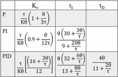
The Cohen-Coon paper is here. The relevant quantities and formulae, with other conventions' symbols and descriptions in blue, are

  • L = dead-period lag = θ = deadtime
  • Z = process time constant = τ
  • M = process sensitivity = K = ∆PV/∆CV at steady state after CV disturbance
  • R = unit reaction rate = M/Z = K/τ
  • μ = RL/M = L/Z = θ/τ
  • S = Controller proportional sensitivity = υ2/(RL) = Kc = ∆CV/∆Error = (τ/(Kθ))υ2
  • U = Reset rate = υ1/(Lυ2) = 1/Ti
    • Ti = 1/U = integral time = Lυ2/υ1 = θυ2/υ1
  • T = derivative time = Lυ3/υ2 = Td = CCW/Micro800 PID_GAINS.FC ;) = θυ3/υ2
  • P-only tuning (no I, no D)
    • υ2 = 1.03 + 0.35μ
  • PD tuning (no I)
    • υ2 = 1.24 + 0.35μ
    • υ3 = 0.34 - 0.11μ
  • PI tuning (no D)
    • υ2 = 0.9 + 0.083μ
    • υ1 = 0.27 + 0.6μ
  • PID tuning
    • υ2 = 1.35 + 0.25μ
    • υ1 = 0.54 + 0.33μ
    • υ3 = 0.5
I switched to a different font because the default font does not seem to handle upsilon very well.

Also, I found what appear to be equivalent versions of those tuning rules in other places e.g. this


xxx.png

and this (g_p = M = K and t_d (not Td) = L = θ):


CohenCoonRules1.png
 
Aaaaaaahhhhh ... the penny drops.

jtvedit-jane-villanueva-jtv-7bIpAGO4sJy4E
giphy.webp


In a word: yes.


No, but maybe they do serve to communicate the facts to those who cannot otherwise see.
You should have just said in post #8 that Rockwell switched the how Td and FC were used. From what was written it was hard to tell if it was your mistake or Rockwell's mistake. I was giving the benefit of the doubt to Rockwell. OK, bad.


Wow, did Rockwell ever screw up on this one.
 
You should have just said in post #8 that Rockwell switched the how Td and FC were used. From what was written it was hard to tell if it was your mistake or Rockwell's mistake. I was giving the benefit of the doubt to Rockwell. OK, bad.

I did; From post#8:

The first thing to note is the magnitude of the derivative response is not determined by the .Td member of the PID_GAINS object, as one would expect from the common and conventional [Td*dPV/dt] form of the derivative term; rather the response magnitude is determined by the .FC member, which the CCW PID help documentation calls a Filter Constant. But "What's in a name? that which we call a rose - By any other name would smell as sweet." The second thing to note is that the units of .FC are seconds.
 
I was giving the benefit of the doubt to Rockwell. OK, bad.


That's an acceptable explanation for your response to post #8, but I have to ask why you continued to do so for so many posts after that.


You've had a successful career; one thing I know about a successful career is that it involves paying attention. So what happened here? Why did I have to say that .FC is the derivative time in six different posts and yet you still asked:


Are you trying to tell us the CCW mixed up the filter constant, FC, with the derivative time constant, Td?


Go back and read what I wrote. Was it somehow unclear? Seriously, if I can't communicate a simple thing like that, I need to rethink how I write.
 

Similar Topics

So I am using a Micro850 and I downloaded the RA_PID UDFB for tuning the temperature of my Thermocouples(TC). I am not sure if I am using enough...
Replies
0
Views
1,420
Can someone tell me what i am doing wrong here? I have set the limits of the CV value for 5min and 60max. The output of the PID is not staying...
Replies
1
Views
1,591
Hi there, I have a small heating system with a micro 830 PLC to assist with the learning process of automation and PLC's etc. The system is a...
Replies
11
Views
8,297
My company built a small test machine using a Micro800 PLC and CCW software. We chose the Micro800 because the machine is very simple. We are...
Replies
2
Views
140
Back
Top Bottom