Linear Actuator Force Control Advice

It took a long time but you finally convinced me. Components are cheap. Effort and lost productivity is expensive. Since it is what we do many of us undervalue the cost associated with our effort. I suspect Jieve has paid for a new actuator, enclosure and power supply a couple times over at this point.

I would surmise that perhaps half of the inquires on this board are describing a task/project analogous to someone using a wrench to drive in a nail. Can you make it work? Sure, but obviously not the ideal tool for the job, nor will it provide the best results. We've all done it and been there and will likely do it again. 🙃
 
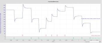
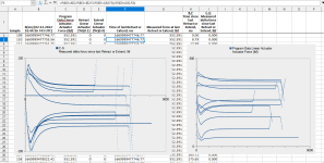
As requested by Jesper, see attached traces and .xls file. The overshoot does look relatively consistent across the board, but haven't tried to analyze it yet.

Force Feedback Trace.jpg
 

Attachments

  • Trace.xlsx
    285.1 KB · Views: 5
So one idea I have based on this data is the following:


For different starting forces, I know the on-duration and how much force was increased once stabilized. From this, I can calculate a rate of change of force vs. starting force. Then curve fit from the data points (I've done this, it's "relatively" linear). The coefficients are different for extend and retract, since for retract I'm fighting the spring force and extend I'm moving with it.


From this curve fit, I think I should be able to calculate an on-time duration that should get me in the ballpark from whatever starting force I'm at with a target force in mind (not exactly sure yet if I need to integrate this curve from starting force to final force to get the time, or what the math is behind that exactly). But in that case, I'd only be using the starting and ending forces, and not dependent on the transient sensor force readings. Actuator SSC-On is only dependent on this time calculation.


As an aside, looks like in general, force stabilization time is between 2-3 seconds generally.


Thoughts?
 
I really didn’t think I wanted reply again to this thread but watching you guys beat your heads ageist the brick wall so it thought I would try and help you out again
Some of you may not agree with this but I have done many torque control systems. Modern crane hoist controls do just that, suspend 100% hoist capacity at 0 speed on the motor without setting the brake
In this application you are trying to maintain tension on using a lead screw driven by a motor. That means controlling torque on the lead screw / output torque of the motor.
The first thing you need to understand is that a motor running at 0 speed / rpms produces 0 torque
It must be moving to produce torque. A motor will produce 0 – 100% torque from 0 speed to the base speed of the motor.
You can use a PWM control to control the on off time of the SSR but it is still just that
And for the power FETs you referenced they work the same they are either full on of full off ( All FET’s work that way ) FETs are used with DC current while SCR’s can only be used with AC Currents
With all SSR’s they are either fully on or fully off there is no in between so they need to be controlled
with a good PWM control, but even with a good PWM control you are still just going from 0 torque to 100% torque very rapidly and you are hoping that you can find a PWM point that will give you the good average torque you need. That’s very difficult to do at best and the more components you have in the control loop the more difficult it is to control the output. Each component to have in the loop adds both a time delay and error to that control loop both of these work ageist you. With a PLC you have many components in play, input cards, output cards, processing time, IO update times and more all play their part and all need time to do their job and each will generate an error and add that error to the final output.
Then keep in mind the SSR’s usually use SCR’s for their internal power control. You have to understand that SCR’s can only turn off when the current through them goes to 0 and while SCR’s can normally turn on at any point in the ac cycle ( that’s how DC drive generate the variable output voltage supplied to the motor ) but in this application it was stated that he is using zero crossing SCR’s that means that the SCR will only turn on or off when the current through them / voltage differential is at 0. So they are either off or on at 100%. ( They do to help eliminate electrical noise in the system )This works well for heating application but not so well for torque control. Then you have the problem of using a dc motor, dc motors don’t handle high torque at very low rpm’s very well. You need high current to develop high torque. High current at low rpm on a dc motor will burn up the commentator. I have seen this many times, that is why they used magnetic clutches years ago. They could control the shaft output torque while leaving the motor run at full speed.
That’s why as I stated before your best option for this application is a good Flux Vector drive. It will give both the full torque control and speed control you need through the full range of the motor and drive. With the correct motor drive combination they can produce 100% torque at zero speed 24/7 365 if that what you need. One word here if you actually look at a flux vector supplying torque at 0 speed what you will see is the motor output shaft will be in motion pulsing a little that is normal, remember the motor develops 0 torque as 0 speed so the drive must keep it in motion to develop the torque. Witch is exactly what you are trying to do with the plc and a pwm output to the dc motor. But in this case the drive is designed to do this and can do much better then you or I will ever do in a plc. So the choice is yours you can chose to use a lot of time and resources to develop something that may just work or just upgrade to something what will do what you want.
 
Thanks for deciding to chime in again :)


The first thing you need to understand is that a motor running at 0 speed / rpms produces 0 torque
It must be moving to produce torque. A motor will produce 0 – 100% torque from 0 speed to the base speed of the motor.


Actually, this isn't a torque control problem, as the trapezoidal screw in the actuator is self-locking. Once it stops moving, it stays there pretty well despite the load on it. The problem that we're (or I with the help of those chiming in) trying to solve is the problem of getting to the force setpoint (within tolerance) despite the fact that the feedback signal overshoots when the actuator is switched off.
 
From this curve fit, I think I should be able to calculate an on-time duration that should get me in the ballpark from whatever starting force I'm at with a target force in mind (not exactly sure yet if I need to integrate this curve from starting force to final force to get the time, or what the math is behind that exactly). But in that case, I'd only be using the starting and ending forces, and not dependent on the transient sensor force readings. Actuator SSC-On is only dependent on this time calculation.


Thoughts?


Extend

Id = (P_tg - P_curr) / (0.5458 + (P_curr + P_tg) * -0.000126)

Retract

Id = (P_curr - P_tg) / (0.7633 + (P_curr + P_tg) * -0.0001624)
 
I have not had enough time to look at this, but just looking at the picture a lot is cleared up. There is a tiny bit of overshoot (probably from the actuators own inertia), followed by what for lack of better word I would call spring-back.

The way the force increases sharply when running the actuator, followed by increasing for a minute time after stopping, and then slowly dropping back significantly does not look like a spring being compressed. It looks more like a material that has some plasticity.
I think we all assumed until now that the spring presses onto some hard stiff material. The way the force settles way back tells us there is more to this.

I think that it might be possible to establish a relation between how much time the actuator has to run, how much change in force is achieved after settling, compensated for the force value working point.

I would run a lot more tests and analyze the data to find patterns and variations.

Other solution could be to run slower. Like a lot slower.
 
Any model is gonna be by guess and by gosh, because there is a bit of noise in those data: the largest and smallest overshoots when retracting (i.e. against the spring) are at the two highest spring compressions, and one of those actually shows an undershoot.
Untitled.png
 
Last edited:
Before going too far into modeling, it should be simple to code the following algorithm:

  1. When retracting against the spring, stop (change %Q0.1 from 1 to 0) when the measured value is ~50lbf below the target.
  2. When extending with the spring, stop (change %Q0.0 from 1 to 0) when the measured value is 0-10lbf above the target.
  3. I expect that will always settle at 50-100lbf below the target,
  4. At which point retracting in steps via PWM with a 30ms duty cycle and 2-3s per cycle should get you there.
    1. I suspect the duty cycle and/or the cycle time could be variable and dependent on how far the measurement is from the target.
Also, those settling characteristics look exponential-ish, so the code may be able to model and predict the asymptote after a second or so of settling, which might allow decreasing the PWM cycle time.
 
It’s clear that some among us don’t understand how an electric motor works and most people don’t really care. All they care about is the motor rotates and dose the work asked of it when we supply power to it. I was going to post an attempt to explain some details on how a motor works but I feel that if you are really interested you should do research yourself
Peter you answered you own question “ It does no work but if current is running through the armatures it produces torque” the only work a motor does is produce torque the amount of torque depends on a lot of things in short all rotational work is toque and as I stated if the armature is not moving it produces 0 torque / 0 work.
I still stand by my original statement the best way to do this application is to use a good Flux Vector Drive with it you have Speed control, Torque control, consistent controllable acceleration and deceleration rates and it can all be done within the drive itself shorting the control loop time any plc will have minimal interface. Any DC motor is a very poor choice for this application and it will never provide you with the consistency and repeatability you want.
 
I realized it's been about a month since I posted this question, and wanted to thank those who participated in the discussion. A few days after my final post I was able to find a decently functional solution to the problem using a combination of the suggestions here.


Just for fun, here's what I did:


Since I was getting the strange load cell signal overshoot and couldn't quite isolate where it was coming from, I did a large number of tests starting at different load values, and pulsing the actuator on for different fixed durations. For example: Start at 200 lbf, pulse for 30ms. Wait for the force to stabilize, then copy down the stable value. Then again for 40ms, then 50ms, etc. Then start at 300 lbf, repeat. Etc. From this, a pattern became clear. Subtracting the starting load from the final load, there was a more or less linear correlation (except during acceleration) between pulse duration and change in force (as was expected through the spring load mechanism, but the load cell overshoot was making the actual values somewhat questionable). I carried out this process for both extension and retraction, and curve fit the data. From the resulting equation, I could calculate an on-time pulse duration based on starting force and desired final force.


There are 3 tolerance ranges. The actuator uses this strategy if the force difference is outside the largest tolerance range. If within the large tolerance, but outside of the second range, then I just use short pulses of 30ms to bring it into the final tolerance range.


When setting a new force setpoint, often no additional short pulses are needed, but if they are, it's generally only 1 or 2.
 

Similar Topics

We are looking for using a linear actuator, with stroke of 780 mm, with force of 2000 to 10000 N, and powered by 24V. It has to be industrial...
Replies
4
Views
877
Hi, We want to buy a linear actuator 24VDC. We want to control this with a circuit board fro electromen...
Replies
8
Views
2,295
I have a SMC Linear actuator rated at 24vdc. 2 wires, do I assume I apply 24vdc to make it go one way, and reverse polarity to make it go the...
Replies
8
Views
2,066
A R&D project, designing sort of a DENSI-METER (hardness tester), to check density of soft products. Looking for a compact version of a motor to...
Replies
1
Views
2,294
The below text is a copy of a web site I just created (1-8-03) to find information on how to solve a seemingly easy but diffcult problem of...
Replies
39
Views
11,199
Back
Top Bottom