Linear Actuator Force Control Advice

It looks like itÂ’s time for a total redesign and rebuild


The inevitable "throw it all away, garbage!" response, there's always one of those ;)


I agree with everyone who has said PWM with a DC actuator would be a more controllable solution. The thing is, if there were no massive load cell overshoot due to the high accel/decel, it would be easy to use the SSR solution and have it stop within the original tolerance range I stated at the beginning, even with the cycle time and zero-crossing delays. I would argue that not forseeing this was probably the thing that wasn't done correctly. A smooth load cell response would mitigate most of the issues here.


Unfortunately a DC actuator would have meant a 15+ Amp DC power supply, additional enclosure cooling, and a larger enclosure. Based on those trade-offs, the decision was made to use an AC actuator. Right or wrong, it's what I'm dealing with.


The motor is built-in to the actuator, so retrofitting a stepper isn't an option.


I'm also not convinced that a PLC is too slow for this.


I can make this system work by simply inching for 30ms, wait for 1 second, 30ms on, wait, etc. until within the tolerance range. Or 50ms. Or 70ms. It would work, but take longer to reach the setpoint, and would be a bit of a crude solution. I was hoping there might be a better way to implement smoother motion with the existing actuator, ideally programmatically.


I think the mentions of using a VFD or similar are on the right track for the AC actuator, just not sure how this would work as the actuator is single-phase (how do you reverse it?). And the extend/retract leads are separate, this is phase-neutral. Ramping up and down the current to the actuator seems to me that it would provide the smoothest motion without the load cell dynamics issues, as Jesper mentioned.


Think using single-phase electronic soft-starters with on-off control might work within the spec'd tolerances?


Thanks again everyone for the input.
 
Single phase VFDs are touchy little beasts. You need to have a PSC or shaded pole motor for them to work at all. My guess is the motor you have in the actuator is PSC but that would have to be checked. Even then the control will not be great. Most of the info I find with single phase VFDs seems to indicate that they works fine with pump and fan loads but not so great with constant torque loads. They can't generate much torque at low RPM, which is an absolute requirement given what you are trying to do.

If you have to stick with the parts you have I would say pulse away. That is about the only viable solution you have.

Keith
 
So would you then use the impulse duration as the maximum "off-time"? Or "predict" the settled force value based on the slopes and use that as the "current" value? Or how would you use this exactly?

I'm not a native speaker, so I don't understand your question clearly enough.

Therefore, I will try to show how I propose to use the pulse duration.

I'm trying to find the period of time (Impulse duration Id) the motor needs to run for the load to change from the current value (P_curr) to the required value (P_tg).

#1 I want to get as much resolution as possible within that 0-750lbf range,
#1 By switching the SSRs on a timer for a 30ms pulse, I’m able to get force increments of about 10-15lbf per “on-Step” at the lower end of the force range, and 3-5lbf at the mid-upper range.

Calculate the coefficients of the formula

Minimum load P_min = 0 lbf
Maximum load P_max = 750 lbf
Rate of load change at minimum load Rp_min = 15 lbf / 30 ms = 0.5 lbf/ms
Rate of load change at maximum load Rp_max = 3 lbf / 30 ms = 0.1 lbf/ms
Rate of load change at current load Rp_curr = Rp_min + P_curr * (Rp_max - Rp_min)/( P_max - P_min) = 0.5 lbf/ms + P_curr * (0.1 lbf/ms - 0.5 lbf/ms)/( 750 lbf - 0 lbf) = 0.5 lbf/ms + - 0.4 lbf/ms /( 750 lbf) = 0.5 lbf/ms + P_curr *(- 0.00053 1/ms)
Rate of load change at target load Rp_tg = Rp_min + P_tg * (Rp_max - Rp_min)/( P_max - P_min) = 0.5 lbf/ms + P_ tg *(- 0.00053 1/ms)
Average rate of load change at current and target load P_a = (Rp_curr+ Rp_tg)/2 = Rp_min + (P_curr + P_tg) /2 * (Rp_max - Rp_min)/( P_max - P_min) = Rp_min + (P_curr + P_tg) / 2 * 0.00053 = 0.5 + (P_curr + P_tg) * -0.000267

Impulse duration Id = (P_tg - P_curr) / P_a = (P_tg - P_curr) / (0.5 + (P_curr + P_tg) * -0.000267)

Try to set some value target load P_tg (in my example 500) and current load P_curr (in my example 150) and calculate Impulse duration Id.

Example:
P_tg := 500 lbf
P_curr := 150 lbf

Id = (500 lbf - 150 lbf) / (0.5 lbf/ms + (500 lbf + 150 lbf) * -0.000267 ms^-1) = 350 lbf / (0.32645 lbf/ms) = 1072 ms


Then set calculated value (in my example 1072 ms) as timer setup. And see how close the load value (after the motor has been running for the specified amount of time) will be to the target load.
Then recalculate Impulse duration Id with new P_curr value. Then set calculated value as timer setup. And so on…

I suppose the experiment takes 10 times less time than I wrote all this)))

I need to see if I can look at the feedback signal on a scope or record them somehow.

That’ll be grate but I suppose it’ll be faster and simpler to find coefficients using trial and error (I think coefficients for load up and down should be different).
 
Last edited:
This whole topic reminds me of the weighing system we are using.
There is also the issue with overshoot, i.e. material being added to the weight when the feed is turned off.
You can do many things to try and weigh precisely, but the simple solution that we use is to measure how much additional material (in your case how much force) is loaded after stopping and settling time. This 'tail' is then memorized for the next run. Instead of aiming for the desired setpoint, the feed is stopped at the desired setpoint minus the previously measured tail.
This works very well for us. We get a repetitive precision of 0.1% of the weighed batch size.
The key is that the process is repetitive. The feed speed must be practically uniform.
This does not require any powerful PLC, or a special motion controller or additional sensors.

An improvement to increase the precision is to run at a reduced speed when approaching the final value (i.e. add a VFD to the feeding motor), to reduce the change in measured value per time unit. But the requirement is that the process doesnt change fundamentally when running at the slower speed.
I dont know this kind of self-locking linear actuator. Does it possibly behave differently when running at the slower speed ?
 
This whole topic reminds me of the weighing system we are using. ... "tail"

+1.

an analogous problem has been solved many times. search the forum for the words tail and spill, and maybe others I can't remember.

If the overshoot is 60lbf when running 100% PWM i.e. continuous, stop at (P_tg - 100), wait 1000ms, then creep up with 30ms pulses from there.

Or even vary the pulse width, say starting at 480ms, with a 1000ms wait time after each pulse, then a measurement, then calculate the change, ΔF, from the previous post-1024ms-wait measurement, and halve the pulse width when the last measurement reaches (P_tg - ΔF). Stop halving the pulse width when the width gets to 30ms, and/or exit the algorithm when the measurement is within tolerance or exceeds the target. The overshoot may not be linear with pulse width, but it should be monotonic, so some fraction other than ½ might be a viable solution.

A handful or maybe a dozen of rungs/statements should be adequate to implement such an algorithm.
 
The whole concept of using PWM is wrong unless the pulses are very short. So short that the system doesn't react to just one pulse but instead integrates a lot of very short pulses. The fact the pulse causes a noticeable acceleration is bad. Acceleration is due to force and that shows up on the load cell.


We don't know the response time of the load cell. We recommend a band with of about 4K.

Once axis force control is easy. This is a little harder.
https://deltamotion.com/peter/Videos/SyncPosForce.mp4

I wanted to add. You can see a rubber cushion that gets squeezed in the video. This makes the system MUCH easier to control. This is similar to the spring in Jieve's system. This is good. Just fix the controls.
 
Last edited:
They aren't talking about PWM, Peter. They are talking about bang-bang control with variable bang times. Then wait for the accel force transient to settle and see where the force really is.

It took a long time but you finally convinced me. Components are cheap. Effort and lost productivity is expensive. Since it is what we do many of us undervalue the cost associated with our effort. I suspect Jieve has paid for a new actuator, enclosure and power supply a couple times over at this point.

Keith
I know jieve was not using a true PWM generator and that his pulses were crude.


This should be easy. I would have had this done long ago even with a DC motor. In fact our sales guys/regional sales managers have a setup similar using a small DC motor. Carrying around a hydraulic system isn't feasible.
 
[FONT=&quot]
Then set calculated value (in my example 1072 ms) as timer setup. And see how close the load value (after the motor has been running for the specified amount of time) will be to the target load.
Then recalculate Impulse duration Id with new P_curr value. Then set calculated value as timer setup. And so on…
[/FONT] [FONT=&quot]I like this solution, rather than using the force measurement, the manufacturer provides speed/load curves, which I can use to calculate the required impulse duration ... so upon setting the force, simply run for the timer duration, then use the remaining force difference to inch at 25-30ms the rest of the way. I might give this a shot.[/FONT]

[FONT=&quot]
How about stating the make and type of actuator and motor, or at least the technical specifications
[/FONT]
[FONT=&quot]The actuator model is a Thompson Linear K2G20-115V-BR-06. I see that they do make these with a 90V DC motor, guess that with a low power DC drive could be an option ... of course lead times are at least 3 months out.[/FONT]

[FONT=&quot]
You can do many things to try and weigh precisely, but the simple solution that we use is to measure how much additional material (in your case how much force) is loaded after stopping and settling time. This 'tail' is then memorized for the next run. Instead of aiming for the desired setpoint, the feed is stopped at the desired setpoint minus the previously measured tail. An improvement to increase the precision is to run at a reduced speed when approaching the final value (i.e. add a VFD to the feeding motor), to reduce the change in measured value per time unit. But the requirement is that the process doesnt change fundamentally when running at the slower speed.
I dont know this kind of self-locking linear actuator. Does it possibly behave differently when running at the slower speed ?
[/FONT]

[FONT=&quot]The motor does slow down a bit under higher load, so the overshoot isn't always consistent, it depends where in the load range it is. But to be honest I haven't measured the load cell output on a scope so I'm not 100% sure what it looks like throughout the entire range. I used a crude method of pulse for 30ms, stop wait, record max and settled values, then rinse/repeat to measure the overshoot for the pulses. And the same method brought the 60lbf number ... by running it full speed and then releasing, running then releasing, etc. This is an interesting idea though, I'll have to think a little about how I would measure the tail; do you just look at the load cell value when the actuator turns off, then again 1000 ms later, or something similar to this?[/FONT]

[FONT=&quot]
If the overshoot is 60lbf when running 100% PWM i.e. continuous, stop at (P_tg - 100), wait 1000ms, then creep up with 30ms pulses from there.
Ah, yeah I like this solution also, I think using the pulses to make up the last part of the motion, no matter what method is used to start is a great idea.[/FONT]

[FONT=&quot]
Or even vary the pulse width, say starting at 480ms, with a 1000ms wait time after each pulse, then a measurement, then calculate the change, ΔF, from the previous post-1024ms-wait measurement, and halve the pulse width when the last measurement reaches (P_tg - ΔF). Stop halving the pulse width when the width gets to 30ms, and/or exit the algorithm when the measurement is within tolerance or exceeds the target. The overshoot may not be linear with pulse width, but it should be monotonic, so some fraction other than ½ might be a viable solution.
[/FONT]

[FONT=&quot]Actually, currently what I've done is something similar for test of concept, I created a "slow PWM" function with timers, set duty cycle to 10% and cycle time to 250ms. This gets me pretty granular force control with minimal overshoot, although it's not the fastest method. I can use the +/-10lbf load tolerance and it works pretty well. The things I don't love about it, is I feel like these on-off pulses could over time cause threads to loosen (used loc-tite on everything), and the speed isn't great, but it does at least work. And now I can refine it with some of the other suggestions here ... including the next idea, which was to refine the pulse durations based on the difference in actual force vs. setpoint.[/FONT]

[FONT=&quot]
It took a long time but you finally convinced me. Components are cheap. Effort and lost productivity is expensive. Since it is what we do many of us undervalue the cost associated with our effort. I suspect Jieve has paid for a new actuator, enclosure and power supply a couple times over at this point.
[/FONT]
[FONT=&quot]Not quite yet, but isn't education also worth something (and not cheap)? While I don't have the luxury of infinite time and money, is there not something to be said for experimenting with different creative solutions to a problem, within reason? As long as you're not excessively wasting weeks worth of time, the experience you gain from experimenting with different solutions allows you to carry the ones that DID work forward to future projects, helping you solve future problems better and faster (i.e. save time and money, for the manager types).
[/FONT]
 
First of all, I think that the system Jieve described is not very suitable for fine position control. I have questions about almost every element of the system.

But as long as Jives has what he has, I will act within the given limits.

I wrote many formulas but few explanations

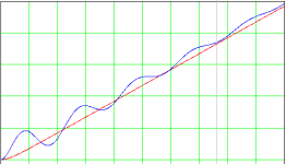
1. Why feedback control "on the fly" is not possible

The picture below shows the actual load curves I assumed (red curve) and load cell readings (blue curve). The same thing happens when the actuator stops. With different loads, the amplitude, possibly, the frequency and damping will be different, and when taking into account possible nonlinearities, signal sampling over time (PLC scan), the restoration of the actual value of the load turns into a complex mathematical problem that cannot be applied in practice.

2. Why calculating the pulse duration to move to a target position instead of multiple pulses.
I am not an expert in electric motors, but as far as I know the transient process in the motor is not the best mode. With multiple short pulses, the motor will operate in transient mode only. The mechanical part of the system will also break down from shock loads. Therefore, it is advisable to try to reduce the number of impulses

The formula that I gave above is suitable for an ideal (theoretical) process. Therefore, I proposed to test its applicability by setting the values calculated by the formula (using any means for calculations) as the timer setting. Perhaps real conditions will require major changes to the formula, or perhaps they will show its complete inapplicability. In any case, before developing a strategy for further solving the problem, it is necessary to obtain the results of the proposed solutions.

load cell reading.png
 
This is an interesting idea though, I'll have to think a little about how I would measure the tail; do you just look at the load cell value when the actuator turns off, then again 1000 ms later, or something similar to this?
Essentially yes. You turn off the actuator, and then you wait for so long that all the 'funny' stuff has settled. Then you measure again and calculate the tail. You can also do some averaging on this tail value if there are slight variations between actuations.

The motor does slow down a bit under higher load, so the overshoot isn't always consistent, it depends where in the load range it is.
If the overshoot isnt consistent, then it may be a dealbreaker for this principle.
I think that it may constitute a problem no matter which principle you use to reach the set force value.
Can you establish a function curve for the overshoot based on the load ?
 
PLC is a Siemens S7-1200 if it makes any difference.
Use the Trace function to record an entire sequence, from before start of the actuator, till so long after stopping that the force has settled completely.
Trace the raw force value and the start signal to the actuator.
Post a picture as well as the trace exported to CSV.
That will give us a better understanding on what is going on.
https://www.youtube.com/watch?v=gve4SeJOTk0
 
Use the Trace function to record an entire sequence, from before start of the actuator, till so long after stopping that the force has settled completely.
Trace the raw force value and the start signal to the actuator.
Post a picture as well as the trace exported to CSV.
That will give us a better understanding on what is going on.
Will do this tomorrow as soon as I have the system back in front of me.
 

Similar Topics

We are looking for using a linear actuator, with stroke of 780 mm, with force of 2000 to 10000 N, and powered by 24V. It has to be industrial...
Replies
4
Views
873
Hi, We want to buy a linear actuator 24VDC. We want to control this with a circuit board fro electromen...
Replies
8
Views
2,291
I have a SMC Linear actuator rated at 24vdc. 2 wires, do I assume I apply 24vdc to make it go one way, and reverse polarity to make it go the...
Replies
8
Views
2,061
A R&D project, designing sort of a DENSI-METER (hardness tester), to check density of soft products. Looking for a compact version of a motor to...
Replies
1
Views
2,291
The below text is a copy of a web site I just created (1-8-03) to find information on how to solve a seemingly easy but diffcult problem of...
Replies
39
Views
11,190
Back
Top Bottom